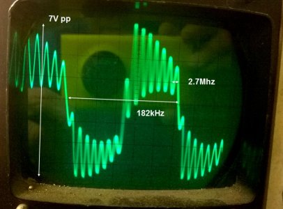
Hi,
Based on previous work by many others including "Otterbox wireless charging mod" by Cubanaso
Cheap Charging Mod + Case
Uses:-
GENUINE Nokia Lumia 925 Wireless Charging Cover CC-3065 (ebay item.321826141838) ?3.99
plus
S-Line Wave Silicone Gel Case Cover FOR Nokia 1020 (eBay item.171183008287) ?1.79
or probably any other Gel case.
Total Cost ~ ?5.80 ish
Needs :-
Soldering Iron and solder
Stanley Knife (or similar)
Wire cutters
Short bit of thin wire - 10cm max
Vinyl Tape
Useful:-
Heat Gun / Hair Dryer
Double Sided Tape if attempting to mount in case (or thin foam like "3 M" cheap stuff on eBay)
Lots of patience !
Method...
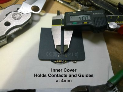
You have to get the coil and contacts out of the case back, then remove the central contact and move the 2 remaining to 4mm apart.
I cut the PCB in half and trimmed and repositioned to get 4mm gap.
You could unsolder and move 1 contact closer and re-solder in 4mm position.
You have to make sure there is no electrical path between the contacts on the film PCB - If you don't cut the PCB to move the contacts closer like I did (i.e. you are moving and re-soldering one contact) then you need to remove any path by unsoldering the little SMD resistors that are linking any affected tracks. Check for infinity before connecting contacts to coil in any case.
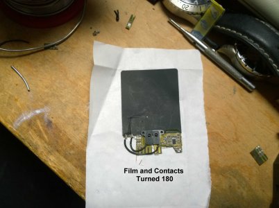
You also have to rotate the film PCB that the contacts are attached to by 180. Destroy any electrical circuit between the contacts and reattach the coil to them using short, thin wires. Reattach the contact cover after removing a little bit of the middle area so that the contacts are kept 4mm apart.
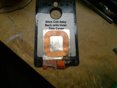
I kept the contacts and cover in place by reapplying the inner surface cover (thin plastic that cuts to size with scissors.
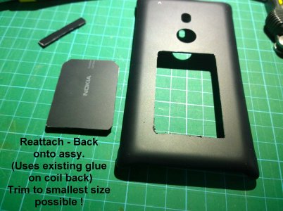
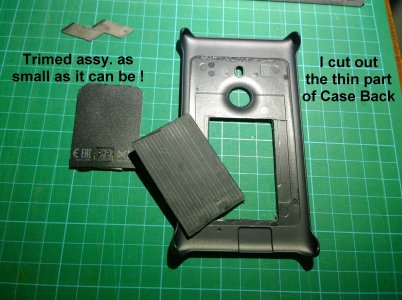
The entire assembly has to be cut to a minimum size (about 1 - 2mm larger than the coil).
I then, after much trial and lots of errors, decided to reattach the Back Plate of the case to add stiffness to the assembly and keep everything in place nicely. This is a piece of the hard back plate that just covered the coil and has the Nokia Logo on it (nice) - the thinnest part of the case but thicker than the phone side thin cover.
This piece may not be necessary and does add some thickness and stiffness but also stiffness.
There may well be a way to do this all without first removing the coil from the back plate by just cutting the whole part out of the back but I haven't tried that method (only one donor CC-3065 Case).
I first tried using the film PCB attached to the coil as is. Just moving the contacts closer together - but - that was when I discovered that space was to tight and the 1020 contacts were mounted the opposite way up to save space. I copied this and rotated them 180 to get them as close as possible to the coil.
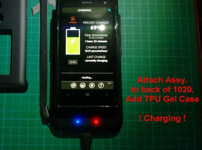
After many trials I managed to get the assembly mounted in the case with double sided foam tape - but - good contact is more hit and miss than I liked, so I mounted the assembly to the phone instead with vinyl tape - checked operation and then fitted the case - Works a treat and if you don't want to keep swapping cases this is not a problem. If you do then you will have to mount in a case or re-attach each time you swap to a case without charging (e.g. Camera Grip Case)
Any Questions ? Just ask ??
(I can't post photos/links into text as too few posts - so editing photos now . . .)
Photos . . .
Attachments
-
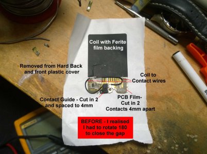 1020-ChargerMod1-01.jpg310.3 KB · Views: 23
 -
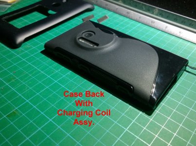 1020-ChargerMod1-09C.jpg276.5 KB · Views: 10
 -
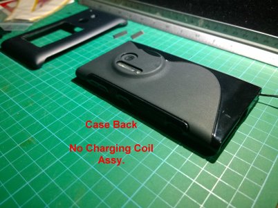 1020-ChargerMod1-08.jpg266 KB · Views: 9
 -
 1020-ChargerMod1-07C.jpg198.5 KB · Views: 9
 -
 1020-ChargerMod1-06.jpg282.5 KB · Views: 9
 -
 1020-ChargerMod1-05.jpg370.1 KB · Views: 11
 -
 1020-ChargerMod1-04.jpg237.7 KB · Views: 11
 -
 1020-ChargerMod1-03.jpg246.4 KB · Views: 13
 -
 1020-ChargerMod1-02.jpg241.2 KB · Views: 16
Last edited:


