Adding Wireless Charging to the Lumia 640

Papek_SVK

New member
Jun 8, 2012
31
0
0
Visit site
Thanks for this DIY...I was thinking of adding wireless charging to my 640 DS. Can you share what size Torx screwdriver you used? Also, did you get a chance to measure the charging time of a complete depleted battery to 100% charged status using only the wireless charging?

Thanks

Now I'm using Lumia 950 DS so I can't tell. L950 uses T5, they should be on 640 too. I gave L640 to my mom since she had outdated Lumia 800.
I didn't test how long take to fully charge battery but I remember it was charging around 20% a hour. +/- 5 hour sounds real. I'm charging my phone overnight and anytime at work when lying on the table so I don't have to worry about battery when I go out.
 

netmann

New member
Dec 6, 2012
140
0
0
Visit site
Now I'm using Lumia 950 DS so I can't tell. L950 uses T5, they should be on 640 too. I gave L640 to my mom since she had outdated Lumia 800.
I didn't test how long take to fully charge battery but I remember it was charging around 20% a hour. +/- 5 hour sounds real. I'm charging my phone overnight and anytime at work when lying on the table so I don't have to worry about battery when I go out.

Thanks. I also have Lumia 920 and looking at the picture of the wireless coil module on the back of the plastic housing, it is sitting in the location that makes the entire coil in contact with the battery, and in turn in perfect contact with my upright wireless charger cradle (Nokia DT-90). So one reason for long charging time could be because the eBay wireless coil module is not entirely in contact with the battery. I also have the following questions:

1) How did you find out the +5v and Ground terminals on the galvanic contacts of the USB Pins?
2) There are four (4) galvanic terminals. Do you know what the other two are?
3) I searched internet for the Lumia 640 Schematics diagrams but I could not find them. Do you happen to find a valid and downloadable link that you can share? Having that would answer my first two questions.
4) What size wiring between the coil and terminals is the best for this mod? I imagine it would be something with low resistivity and high conductivity.

Thanks
 

Derausgewanderte

New member
Dec 18, 2011
1,544
0
0
Visit site
Thanks. I also have Lumia 920 and looking at the picture of the wireless coil module on the back of the plastic housing, it is sitting in the location that makes the entire coil in contact with the battery,

I don't think the receiver coil touching the battery makes any difference. If it does something then it is heating of the battery. The coil produces charge that it transferred wired to the battery, not via induction. The latter only happens between the coil and your qi charger.
Cheers
 

Papek_SVK

New member
Jun 8, 2012
31
0
0
Visit site
Thanks. I also have Lumia 920 and looking at the picture of the wireless coil module on the back of the plastic housing, it is sitting in the location that makes the entire coil in contact with the battery, and in turn in perfect contact with my upright wireless charger cradle (Nokia DT-90). So one reason for long charging time could be because the eBay wireless coil module is not entirely in contact with the battery. I also have the following questions:

1) How did you find out the +5v and Ground terminals on the galvanic contacts of the USB Pins?
2) There are four (4) galvanic terminals. Do you know what the other two are?
3) I searched internet for the Lumia 640 Schematics diagrams but I could not find them. Do you happen to find a valid and downloadable link that you can share? Having that would answer my first two questions.
4) What size wiring between the coil and terminals is the best for this mod? I imagine it would be something with low resistivity and high conductivity.

Thanks
I don't think that speed of charging has anything with distance to a battery. Maybe coil quality, electronics ... I had Lumia 920 and 928 but I really don't remember how fast or slow was wireless charging. Keep in mind that Lumia 920 has 2000 mAh battery, while 640 has 2500. Thats 25% more which should lead to slower charging.

1) multimeter and micro USB cable with open end. I could find there is no diode or anything in the path between pins and contacts
2) rest are data pins
3) I wasnt looking for them
4) as short as possible. I used wires from old USB cable. They are very thin and flexible but works fine for charging.
 
Last edited:

vicu9mx

New member
Mar 16, 2012
20
0
0
Visit site
Once a month do full discharge
Really?? Do you take only the part that say avoid wireless charging and not this part??
[h=3]Never go to zero[/h]
If you're going to be shelving any lithium-ion battery for a long time, try to leave it with at least 40 percent battery power to tide it over. Lithium-ion batteries don't hemorrhage power when their not in use, but they'll lose maybe five to ten percent of their charge each month.
And when lithium-ion batteries get too low—like, literally zero percent—they get seriously unstable, and dangerous to charge. To prevent explosion-type disasters when you go to charge one that's been sitting around for a month or two, lithium-ion batteries have built-in self-destruct circuits that will disable (read: destroy) the battery for good, if it reaches rock bottom. And sure, that'll save you from a face full of battery-acid, but it'll also leave you short one battery.
 

Will Gilliland

New member
Jan 6, 2015
68
0
0
Visit site
... I thought the heat was excessive. ... I tested the top, middle and bottom sections of both front and back on both phones. Here are my readings, all in degrees F.

Galaxy S4
Back Middle 86

Lumia 640 with wireless adapter
Back Middle 100.7
?
My Qi universal receiver tag finally quit working. I order a new one and it's working MUCH better. The back still gets pretty warm, but I wouldn't call it "hot" like my first tag. Folks, I think I just received a bad one the first time. Now I'm much more encouraged to do this mod.
 

Matej25

New member
Jan 13, 2016
9
0
0
Visit site
I just added wireless charging to my 640 LTE. It requires torx screwdriver, soldering skills and little patience. See pictures below.


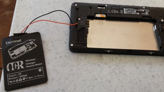
Universal wireless charger module, $3.30 on ebay.

View attachment 118897


Remove battery cover, battery, SIM card, microSD and screws as shown in the picture. There is one screw under the sticker and two screws on the side.

View attachment 118898


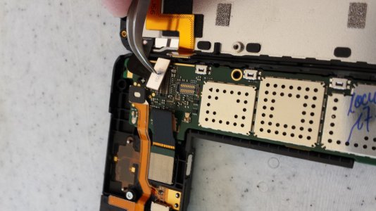
Carefully lift the back part from the right side. and disconnect two flex cables.

View attachment 118899


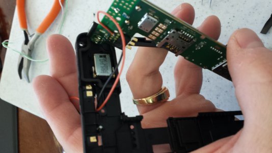
Disconnect camera and audio jack cable on the back part and remove PCB. PCB is held by plastic hooks, so be carefull and don't broke them.

View attachment 118900


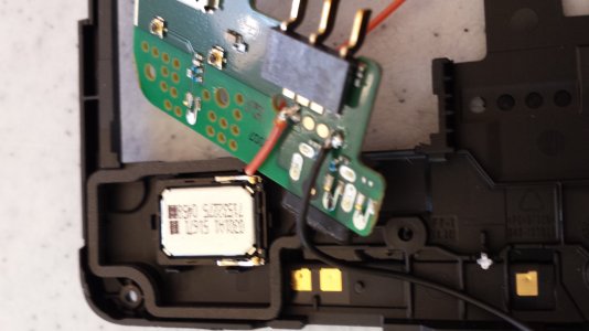
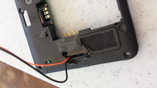
There are four contacts, which are galvanically connected to the USB pins. I soldered very thin wires from old USB cable. Be quick and don't overheat the board. Carefully remove any excess flux.

View attachment 118901


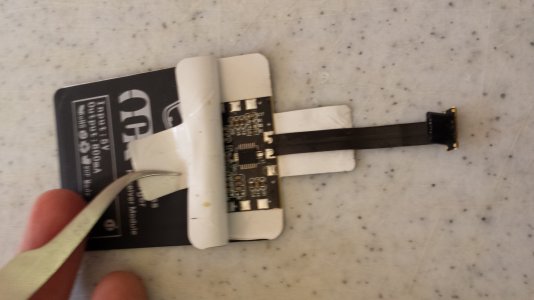
Now you need to modify the module. Open the module and unsolder flex cable.

View attachment 118902


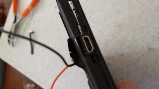
Assembly the phone. Guide the wires through the gap under removed sticker in the back cover and solder them to the charging module. I was little careless and touched the label with solder tip so I cut it away and covered it with black insulating tape.

View attachment 118904


It works! Keep in mind this mod ruins your warranty!

View attachment 118903

Super robota chlape ;)

Nice job buddy ;)

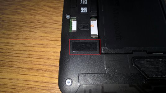
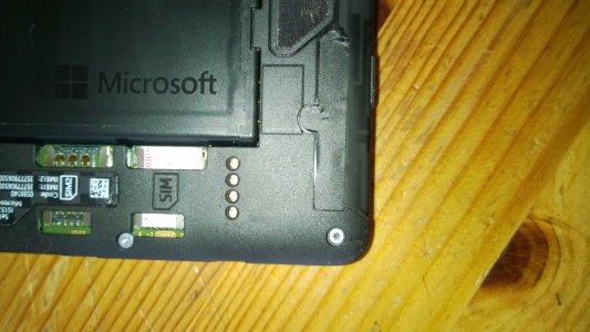
Anyway, I have just studied mine 640 LTE and there is preparation for the wireless charging see my picture below.
Under that black sticker there are 4 holes for the wireless receiver connection and on your picture of PCB on the same place there are 4 contacts which should be connected to USB port (not 100% sure, this needs to be checked).
So there should be option to create back case like the one which 830 has, with the wireless charging receiver included.
WP_20160115_11_23_38_Rich.jpg

118901d1450096050t-06.jpg
 

fangio2

New member
Jan 16, 2016
1
0
0
Visit site
Hello,

I also check my L640 to install the wirless charging (the qi pad from L920).
I found also the 4 pins under the sticker.
Have anybody the service schematic for this Lumia?
Is it similar to the pins at the L640 XL?

WP_20160116_13_50_12_Pro.jpg
 

susanne1188

New member
Jan 17, 2016
1
0
0
Visit site
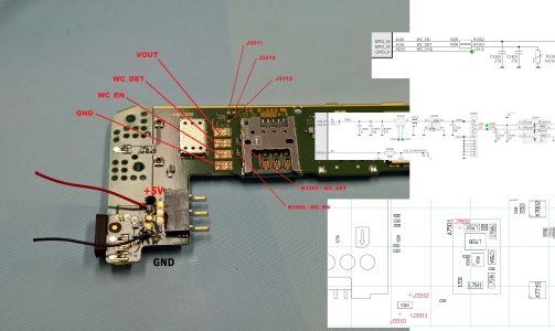
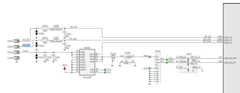
hi i have ever tried out the assignment of the pins . I do not know whether it is right and can not even try ... no lumia phone (but next week :D) about the GND i even havent find in the schematic some about, but should be right. sry bad englisch (mother tongue german) maybe some one try it out or can add / rectify a bit...wc10.jpg
SECOND PIC IS FROM 640XL!!!! (wc11.jpg)

wc11.jpg
 

Will Gilliland

New member
Jan 6, 2015
68
0
0
Visit site
I just added wireless charging to my 640 LTE. It requires torx screwdriver, soldering skills and little patience. See pictures below.
I finally got around to doing this modification to my 640 (AT&T). Your guide was very helpful.
My Qi receiver tag was opposite. I put the tag on a Qi wireless charger to read with a DVM and marked + and -.
20160122_142438.jpg
Like Papek said, remove the screws marked in red with a Torx #5. The sticker hides one of the screws. I went ahead and removed the entire sticker since it's very brittle and you'll need that space anyway to thread the wires through.
20160122_143259.jpg

I used an old USB cable for the wires, also. If you do use the wires from a USB cable, be careful of the hair-like shielding wires that tend to break away. You don't want these falling into your phone.
20160122_143604.jpg

Carefully open the case from the right side and note the camera and data connections. I used curved tweezers to remove the connectors. You will be removing 4 connectors.
20160122_145023.jpg

Remove the PCB carefully. Again, I used tweezers. As Papek noted, it is held in by fragile plastic ears.
Solder your wires on as shown and thread through the slit where you removed the sticker for the hidden screw.
20160122_150821.jpg
20160122_151634.jpg
20160122_151723.jpg
20160122_151723.jpg

After reassembling, I notice my PCB didn't fit flush. There are some leaf spring connectors that do push up the PCB some, but this is too much. The issue was my wires were a little too thick and I had to trim away a little plastic around feed-through slit.
20160122_152033.jpg
20160122_155119.jpg

I left my wires a little a little long to allow me position the tag in the sweet spot.
20160122_160247.jpg

It's all back together and works great. If I were to do it again, I would have used slightly thinner wires. I also made a bonehead move and tried to solder without flux the first time. I was afraid I created cold solder joints so I went back and resoldered using flux and I got the stuck lid off the dang jar of flux. Also, I couldn't find my electrical tape. When I get a new roll, I'll cover up the slit by the hidden screw better and position the tag a bit better.

Thanks for pioneering this, Papek.
 

Papek_SVK

New member
Jun 8, 2012
31
0
0
Visit site
Hah, another daredevil on the scene! Yesterday I tested Lumia 640 with DT-910 charging stand and it works with no issues. So if you place the coil in same place like I did, it should work fine.
Or to be more precise, bottom edge of the coil in my L950 is placed 38 mm from the bottom and it works great too. Too bad (for the others) that MS didn't include wireless charging itself.
 

netmann

New member
Dec 6, 2012
140
0
0
Visit site
hi i have ever tried out the assignment of the pins . I do not know whether it is right and can not even try ... no lumia phone (but next week :D) about the GND i even havent find in the schematic some about, but should be right. sry bad englisch (mother tongue german) maybe some one try it out or can add / rectify a bit...View attachment 120653
SECOND PIC IS FROM 640XL!!!! (wc11.jpg)

View attachment 120654

Susanne1188, Thank you for this lead.

If you have the complete schematic diagrams of Lumia 640, would you mind post it on this thread or post a web link?
Thanks.
 

higonp

New member
Apr 17, 2016
3
0
0
Visit site
I used your guide. Thank you very much. I would add for those not very versed in soldering the method I used was to tin the wires, I did this by putting a little flux on the wires (one at a time) then applying the solder to the tip of the soldering iron (a little molten ball on the tip of the iron) I then then touched that to one wire and then repeated on the other wire. Then I did the same on the pads on the logic/motherboard for ground and pos+ I used a toothpick to apply the flux just to the pads I then put more solder on the tip of the iron and touched the pad on the board and the solder went right into place. Then I took my ground wire and lined it up with the pad and with the soldering iron tip completely clean I touched the wire and the solder on the pad and wire instantly liquified and I removed the soldering iron cleaned tip and repeated for the pos+ wire. The contact with the pads on the board while putting the solder on the pad was about a 1 second and then when applying the wire was about the same so with this method heat to board is very fast and limited.
From previous experience working on other phones plan your attack with the iron to avoid all the little resistors,inducers, fuses chips or whatever on the board and make sure the tip hits only what you are aiming for. Also the best direction in my opinion for the wires was straight toward the bottom of the board almost exactly as pictured in Papek_SVK photo's. I used a dremel tool to cut about 1/3 of the flange away from the black plastic housing where the screw comes through, that flange on the housing will be directly adjacent to where your pos+ wire is soldered on and will prevent logic/motherboard from closing back down flush during reassembly (double check that you are cutting the correct side of the flange away before you cut). I also used curved fingernail clippers to clip away the little plastic ribs (stiffeners) that Will Gilliland posted pics of on his phone on page 3 of this thread. After reassembly I tinned the other end of the wires and attached them to the appropriate pads on the wireless receiver ( the pos+ and ground were marked on the original wire/ribbon cable, so I marked the the pads on the receiver before I cut the original wire/ribbon cable off. My phone housing to logic/motherboard and then to screen fit were all perfect on reassembly so if something is not fitting perfectly then something is wrong don't force it, re-examine your work fix the problem and try again :)
Thanks again for the guide and I hope what I added is helpful to someone.
 
Last edited:

higonp

New member
Apr 17, 2016
3
0
0
Visit site
Flange partially removed and ribs/stiffeners snipped away.


solder on pads.


wires easily attached to pre-soldered pads.


Should fit like this after reattaching board to housing.


Finished.
 
Last edited by a moderator:

mortici

New member
Sep 18, 2013
95
0
0
Visit site
Hello,

I also check my L640 to install the wirless charging (the qi pad from L920).
I found also the 4 pins under the sticker.
Have anybody the service schematic for this Lumia?
Is it similar to the pins at the L640 XL?

View attachment 120601


Looks like its already configured to do it, just the connector pins aren't soldered on. I will see if I can find a source for the pins they use, I think they are similar to that of the Lumia 735, solder the pins on, now you got external contacts, find the proper 4 pin pad tape to inside of case and voila no wires. But the alternate options here work too.
 

mortici

New member
Sep 18, 2013
95
0
0
Visit site
Looks like the Lumia 820 has a 4pin flat contact qi pad on the inside of the case. Now to find the pins that are used in the lumia 735/950 that are soldered on the board and poke through to make contact with the back cover. Need 4.

Combine the two parts (after trimming some of the pad to fit the 640 shell) and you have yourself a wireless charging back ☺

Granted the methods here are cheaper albeit not pretty...

Posted from Windows Central for Windows 10
 

Members online

Forum statistics

Threads
326,589
Messages
2,248,600
Members
428,515
Latest member
vl909