Hi, Folks.
After building these modifications for several months, I wanted to update the procedure one final time to encompass all of the lessons I've learned into a single post, partly because this thread's hideously long, and partly because I'm tired of lazy people contacting me and asking me to do their reading for them, or provide them
"with a quick summary of what needs to be done." (Who knew reading was so difficult!)
To start off, I should point out some facts that I'm aware of:
- AT&T does not sell a Lumia 1520 with the Qi Wireless Charging Capability
- AT&T variants have three gold dots on the back case for connecting to the PMA Charging Sleeve
- AT&T Lumia 1520's do NOT have Qi-capable electronics built in, and you cannot use an International Lumia 1520 case to add this capability
- International Lumia 1520 cases ONLY provide a Qi-compatible antenna, not the associated electronics to use the antenna
- AT&T Lumia 1520's are built to support a PMA-compatible charging sleeve only, but can be hacked to add Qi Wireless Charging by installing a self-contained Qi Receiver
Now that that's out of the way, let's start. I'm not going to cover details like how you open your 1520 or how you solder --there's plenty of information on this already available. I want to focus on the modification itself, and the lessons I've learned over the last 9 months building these modifications. After having used this modification successfully for 9+ months, I know how well it works and how reliable it is. I also know what a pain in the arse it is to build, and for that, I'm sorry. It is what it is. You
will need a Microscope to prepare the flex, or some kind of stable, clear magnification. You will need a very fine-pitch soldering iron and some relatively decent soldering skills to make this work. You will also need to be anal-retentive and meticulous about preparing the flex, or you'll miss something and probably cause a short. Even on a good day, it takes me 1 hour to prepare this modification, and I've had LOTS of practice...
Parts required:
- AT&T Lumia 1520
- Self-contained Qi Wireless Charging Coil, I recommend the Lumia 920 coil (Nokia Lumia 920 Wireless Charging Coil)
- 2mm or smaller soldering iron
- Liquid Soldering Flux
- Kapton Tape 1/2" wide (or other polyamide insulating tape)
- Non-foam, double-sided tape
- Bus wire, solid core, 24 to 26 AWG
- Super-fine X-Acto Knife, new condition
- Digital Multi-meter
- Working Qi Charger (for testing)
- Goop-Off (the nasty stuff that comes in a metal can, not that kid-friendly crap used for removing crayons)
- Lots of fresh Q-Tips... with cardboard sticks, NOT PLASTIC ONES! (You're dipping them in Goop-Off... Have you seen what Goop-Off does to plastic?)
Disclaimer
This is a hardware hack (duh!) and as such, it
WILL void your warranty. You risk irreparably damaging your Lumia 1520. If you attempt to do this work, you do so entirely at your own risk, with only yourself to blame if things go bad. It is up to you to verify the validity of these instructions prior to permanently installing this modification into your device. Make sure you have the skills necessary before attempting this modification.
READ THIS ENTIRE PROCEDURE FROM START-TO-FINISH BEFORE STARTING YOUR WORK!!
Step 1: This procedure assumes you're using the PMA flex already installed in your 1520. If you have the fortune to find a new, unused PMA flex, move to Step 3. Open your 1520 by removing the SIM Tray, uSD tray, white bar-code label, and T2 Torx screw hiding underneath. Pop the cover off the display from the top sides, working your way down to the bottom sides. Once the top and sides are free of the cover, gently lift the bottom out of the cover. If you need more details on this, do a search. ;-)
Step 2: Remove the PMA Flex from the back case of the phone. Use that fancy T2 Torx driver you used to remove the side screw to press the center gold dot on the back case. Press hard enough to pop the sleeve conductor PCB off the back of the case, then gently lift the PMA flex towards the top of the phone. Gently and slowly peel the flex away from the top anchor where the 3 gold square contacts are located to free the flex. It should be completely free of the case now. Set the flex aside and take great care to ensure you don't contaminate the adhesive tape on the top or the bottom of the flex - that includes finger prints, cat hair, hot pocket crumbs or boogers.
Step 3: Remove the 2 black rubber spacers adhered to the inside of the case. Peel them away slowly to avoid shedding adhesive. These will not be used going forward, so decide if you want to save them or not. They work great to prevent elbow chafing.
Step 4: Prepare the Flex. This is one of the two hardest parts of this modification, and this step takes the most time and patience. You want to chemically solve away as much of the black paint and conductive shielding as possible, down to the mylar / orange polyamide insulator. Here's a picture of what you're trying to do for reference:
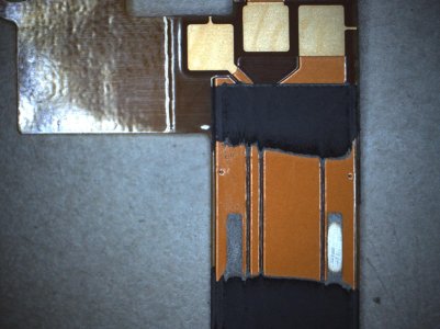
The idea here is that you use solvent (Goop-Off), friction and time to gently wear-away the layers of the flex, in the area shown, gently and slowly to avoid damaging the flex. Sure, you could scrape it, but if you dig into the flex accidentally, it's not easy to repair it - and you've only got one flex, so do it right and be patient! (Side note: I'm experimenting with using a fiberglass scratch brush to speed up this process; I may post more on that later if it turns out to be helpful.)
Saturate a Q-Tip with Goop-Off. Using the picture above as a guide for where you need to clean, start rubbing the Q-Tip on the flex while holding the flex firmly to a solvent-proof table. Make sure the Q-Tip stays moist with solvent. After a few minutes, that side of the Q-Tip will start to turn black, indicating you're getting into the black paint. Keep cleaning. Eventually the black turns into gray conductive paint, and this paint is considerably tougher than the black paint. If you decide to scrape away at the paint or gray coating, do so with something that won't cut or dig into the orange insulating layer under the gray shield coating - like a dull X-Acto blade... All I can tell you is to be patient - it takes 20 to 30 minutes to get this clean as shown in the picture.
Here's the catch... That gray coating is electrically connected to NEGATIVE, and it has a very nasty habit of staying hidden in between the traces. You must get it out of the way of your soldered connections, or else you'll short the flex. Use the fine point on the X-Acto to
carefully scrape it out of those grooves -
without damaging the orange insulating layer. Once your flex looks like that picture, move to the next step.
Step 5: Identify the flex traces and solder points. Here's your picture:
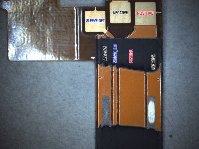
This picture identifies the signals on the flex that you care about. You have NEGATIVE, SLEEVE_DET, and POSITIVE. All of these traces will be used.
Next, mark the zones that will be cut away on the traces to expose the copper underneath. Use this picture as a guide:

The black marks are the areas that need to be exposed. To do that, you need to very carefully use your new X-Acto knife blade to very gently scrape-off the orange insulating layer to expose the copper underneath. Press too hard and you'll cut into the flex, potentially destroying it... Go too fast, and you'll cut more than you wanted to placing you at risk of a short... This is what your flex should look like when you're done:

In the picture, you can clearly see 4 exposed areas that show copper. The one on the far right was a "freebie" that came as a result of cleaning the paint & conductive mask away. You won't use the far right trace - you only care about the first three traces. Also note that the SLEEVE_DET trace (#2 from the left; the thin trace) was carefully exposed while the traces on either side of it where not touched - this is very important! If you short SLEEVE_DET to positive, you may permanently damage your charge circuit (i.e., the phone won't charge via USB or Qi!!)
Step 6: Add double-sided tape to the orange side of the flex as shown below, but do not peel-off the backing yet. This is to adhere the flex to the 920 Qi charging module:

Tin the PMA Flex traces. Add solder flux to the 3 exposed traces, and tin the areas with solder. Do not exceed 750?F or you'll risk delaminating the flex. Also watch your dwell time; try and get done in 4 seconds or less (with each trace). I generally solder at 710?F with a .5mm tip. Once done, your trace should look something like this:
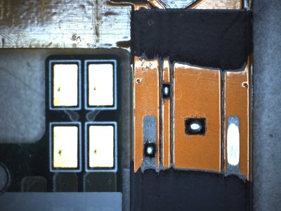
Solder PMA Bus wire jumpers. Using the picture below as a guide, cut & strip bus wires to make the connections to the 920 Qi charging coil. Clean off the flux once finished:
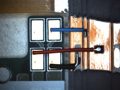
The picture shows where the wires are eventually going to be soldered to. The Blue wire is SLEEVE_DET, and will connect to P2:WC_DET on the 920 Qi Charging Coil. The Red wire is POSITIVE, and will connect to P3:VCharIN. The Black wire is NEGATIVE, and will connect to P4:GND. Note how the wire positions correspond to the plates on the 920 Qi Charging Coil.
That was no accident...
Step 9: Position and adhere the 920 Qi Coil to the PMA flex cable. Peel the backing off the double-stick tape, and position the PMA flex dead-center on the WHITE side of the 920 Qi Coil, gold-contacts facing up:
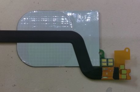
Gently press and firmly adhere the flex to the coil.
Step 10: Solder the 3 wires to the associated Qi Coil Pads. Using the picture below as a guide, use those fantastic soldering skills of yours to complete the circuit as shown below. Make sure you clean off all flux debris once finished:

Watch out for the gold plates on the 920 Coil - they themselves are soldered to the PCB, and when you heat them, they'll float away if you're not holding them in place... You can see how my positive plate turned clockwise a few degrees when I soldered it... If they do come off and piѕѕ you off, just solder directly to the PCB. The gold plates are non-essential.
Step 11: Test the modification (for shorts and proper operation). Using a DMM set to continuity, measure for shorts between +, - and SLEEVE_DET. There should be no shorts to any of these circuits. SLEEVE_DET should NOT be shorted to NEGATIVE; I used to do that in my old mods, but found that it caused certain phones to get stuck in a "charging mode" even when removed form the Qi charger. Using SLEEVE_DET with WC_DET fixes this problem (but requires one more wire to solder). It also enables faster charging, since the impedance on the Negative circuit is now considerably less having been isolated. I
think it also results in the charging coil running cooler, but I can't really back that up with quantifiable data...
Once you verify that there are no shorts, place the coil on your Qi charger and verify that it generates +7VDC between + and -. Also verify that you see +7V between + and SLEEVE_DET. If you do, then you're ready to move on to step 12. If you don't, check your wiring and assembly steps.
Step 12: Insulation and cleaning. Once the soldering's verified and the device is functionally tested, you're ready to insulate those thin, high-quality, low-profile solder joints you created. You DID make them low-profile, DIDN'T YOU?! I hope so... Using a 1/2" piece of Kapton tape, wrap the work site as shown below:

Now use a Q-Tip dipped into 99% Isopropyl alcohol to clean off your hot-pocket-greased diϲk-skinner prints, then clean the three Square Gold Contacts off. Make sure they shine and do not touch them again... finger oil on these contacts is BAD, BAD, BAD.
Step 13: Final check and installation. Does your flex look like this?

If so, you're ready to install it. Peel the backing off the adhesive tape on the top of the flex (if present), the Qi coil, and the bottom of the flex (if present). Re-install the BOTTOM PMA BUTTON PCB FIRST (this is important!). Press it very firmly to ensure that 3 gold dots are pushed back into their holes. Now, align the top of the flex back into the locking pin, and gently scoot the Qi coil into position, allowing it to plant in the center of the case. Everything should be flat once re-installed. If you touch the top 3 gold contact squares while pressing the double-stick tape back down, just clean it up again with a Q-Tip and alcohol. Once you're done, re-assemble the case onto the phone electronics. Remember to insert the BOTTOM part of the phone into the case
before snapping the rest of the phone hardware back into the case. Test the mod before you replace the T2 Torx screw and sticker. Make sure the charging indicator turns off a few seconds after removing the 1520 from the charger (~5 seconds or less, typically). After everything checks out, turn off the 1520 and insert your SIM and uSD card (if you have one).
That's it. I hope the pictures help. Congratulations if you were brave enough to try this modification and actually succeeded!! You have earned a new badge:

SonarTech


