Qi Charging on a LUMIA 1520 AT&T phone (Solution)

unreal69

New member
Apr 20, 2014
1
0
0
Visit site
I've finally made the jump and wanted to document the process and share with the community. It is really not a big deal if you can handle a soldering iron and have some nerves. Following Sonartech's how to's is all you need.

Couple things:

* Scratching off the ribbon connector isn't as easy as I thought, you first have to scratch through the black coating, then through the yellow isolating later underneath.
* I chose to place the coil a bit lower than most seem to because I wanted to make sure the phone would charge Ok in the upright Nokia Wireless charger (DT-910) and the Nokia Car charger (CR-200)
* It took me about an hour on my first 1520 (black), but once done, I upgraded my son's yellow 1520 in about 15 minutes from assembled to re-assembled
* I used and definitely needed a head-mounted magnifier which I got on Amazon for $8 (here)
* I got the two 920 coils on ebay for $8.99 (here)
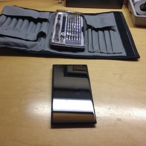
IMG_0679.jpg
Ready to operate

IMG_0680.jpg
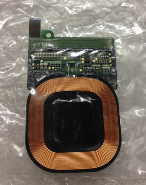
Lumia 920 spare coils for $9 on eBay

IMG_0682.jpg
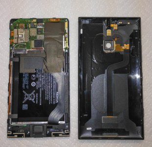
Simply opened, no mod yet

IMG_0683.jpg
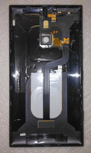
Positioning the coil fairly low in the 1520 body
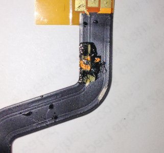
IMG_0687.jpg
Bridging the two tracks (-) and (T-) with a drop of tin, harder than it seems
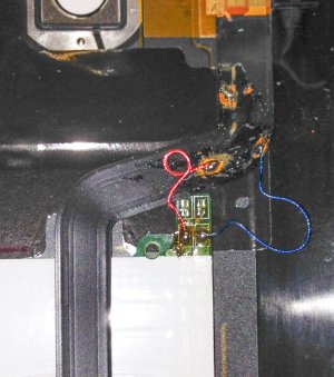
IMG_0689.jpg
I used wires from dead earphones

IMG_0697.jpg
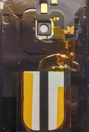
Taped and ready to close

IMG_0699.jpg
My 2nd 1520 mod, on a yellow model. I also re-used some fo the black foam padding on each side of the coil and on top of the flat connector.

All done, this is finally giving me the one missing feature on the 1520. I've got WinPho8.1 loaded and rocking on it now too!

Have fun modding.
Unreal.
 

boscoosco

New member
Apr 21, 2014
5
0
0
Visit site
So I don't want to solder directly to my phone or take it apart (company device, not worth getting fired) but I still want my wireless charging back. Is this solution possible?

1) Buy the wireless charging case
Buy Incipio Wireless Charging Case for Nokia Lumia 1520 - Microsoft Store

2) Remove the crap from inside

3) Solder the 920 coils to the 3 pins on the case

4) Attach case to the 1520 and it becomes a QI charging case

Or would it be possible to solder 3 small wires to the 920 coils and somehow stick them to the 3 pins on the back without solder? Then just use a case to make sure everything sticks together? Where do I find the little pins that are in the charging case? I could solder the wires to pins like that and then use tape to hold it in the perfect spot to make contact with the pins on the back.

There has to be a way to do this without permanently modifying the phone right?

Edit:
So I answered my own question. Went to Radio Shack and spent $20 on misc parts (biggest cost was solder and wire). Put together the below contraption and was able to connect all 3 pins to the external points, and voila wireless charging worked! However I couldn't get it to sit together properly b/c the pins were too big. So trying again with the smaller pins. Please don't judge my poor soldering skills, I'm terrible at this :( Just sharing in hopes someone has a better idea.

Zugusmc.jpg


U5nwau7.jpg


Xh6Dozw.jpg


BdXSTbs.jpg


0aXeNGm.jpg


j1IjtGk.jpg


uZN9t58.jpg
 
Last edited:

boscoosco

New member
Apr 21, 2014
5
0
0
Visit site
So I put the below together, still having trouble keeping the contact points held tight against one another :( So it charges if I hold my fingers down but as soon as I leg to it stops charging. Sigh.

gamsBaX.jpg


NvETON6.jpg
 
Last edited:

Lanceloni

New member
Nov 13, 2012
15
0
0
Visit site
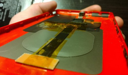
I have successfully modified the international shell to support Qi wireless charging. I could be wrong, but I think this might be the thinnest solution so far (but not the cheapest).

WPCentral.jpg

Here is what you'll need:

One thing to understand that even though the shell you bought online has a coil in it, it is missing a key component... the circuit to change the voltage type. This is what you'll be cannibalizing from the Lumia 925 charging shell. Before continuing, familiarize yourself with the steps from SonarTech in this post. Always remember hacks like this void your warranty, so proceed with caution, patience and knowledge. By following these steps, you agree not to hold me responsible for you messing up your phone.

Step one: Preparation

  1. Remove the back cover to your Lumia 1520 and carefully remove the existing flex cable. It's held with dual sided tape on the bottom and the top.
  2. Take the coil out of the Lumia 925's charging shell. Peel off the layers and de-solder the coil from the circuit board (two wires connect the coil to the board, leave some solder on the board)
  3. The voltage converter board has a black piece of plastic around the metal contacts, you can pry that off from the bottom (take it slow, it takes a little pressure, but will come off). You'll have the three prongs left.
  4. Remove the three prongs on the voltage converter- Bend the metal contacts back and forth until they snap off (or de-solder them, but be careful not to apply too much heat. Pro-tip: leave a little hot solder on the tip of the iron and use that to heat the edge of the pad)
  5. Now, with the new replacement 1520 shell, remove the flex cable and bend it backwards so you can see the contacts from the charging coil.
  6. De-solder the coil from the flex cable and remove the flex cable from the shell. Leave the coil and shielding in place..
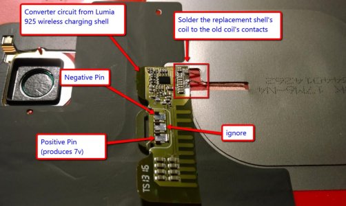
  7. Place the voltage converter circuit on shell and line up the pads where the old coil was soldered, now solder the shell's coil wires to the pads.
  8. Test the voltage place your multi-meter's leads on the left-most and right-most pins on the converter circuit board. You should be getting approx. 7 volts when the shell is on a charger. The pin to right is negative, the pin to the left is positive, the pin in the middle isn't used for our purposes.

Now this is what you should now have:

WPCentralOne.jpg

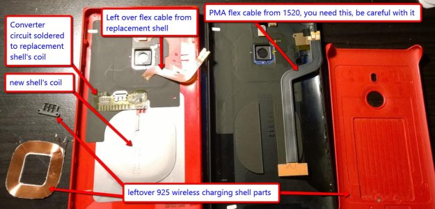
Here's a high overview of what parts should be on your workspace

WpCentralTwo.jpg

Now tape down your work with Kapton tape to secure and insulate it from the next layer.

WPCentralThree.png

Before moving on if you have not read SonarTech's post to learn how to prep the PMA flex cable for soldering, do it now.

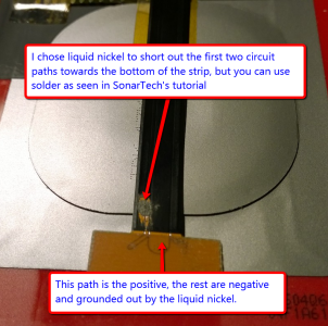
My next step was to short out the two negative flex paths. SonarTech uses solder, but I like my liquid nickel pen for these low profile, low stress connections. When the liquid dries, just the nickel is left and completes the circuit because it is conductive.

WPCentralFour.png

With your flex cable's spots cleaned and ready for soldering, let's continue:

  1. Cut a couple small pieces of wire from the left-over Lumia 925 wireless charging shell's coil (the advantage of doing this is that one side of the wire is pre-tinned).
  2. Pre-tin the exposed spots on the flex cable. This way when it comes time to connect the wire, its literally melt-and-go, no need for additional solder.
  3. Pre-tin the cut ends of the wire (STOP - before continuing, make sure there continuity in the wire. If not, make sure you have properly tinned the wire (there is a very thin layer of nonconductive material so that the wire doesn't short when it's coiled. You can burn this off with the iron or scrape it off)
  4. Line up and snap in the flex cable to the same spot it was on the original case (it will fit exactly). Secure the flex cable to the case with your non-conductive tape
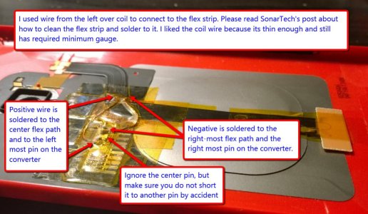
  5. Now solder the wires to the to the converter pins first, with them secured use tweezers to hold the wire down and solder to the right spots on the flex cable (read SonarTech's post). The left pin is positive and the right most pin is negative. Ignore the middle pin.
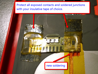
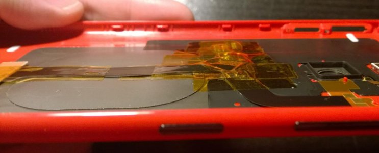
  6. With the wires soldered, use your favorite non-conductive tape to hold down your work.

Here is what it should look like

WPCentralFive.jpg

One last voltage test, put the finished shell on a wireless charger make sure you are getting 7 volts ( IMPORTANT make sure the polarity is correct before putting the cover on, otherwise you will fry your phone's charging circuitry )

Here is the final result!

WPCentralSeven.jpg

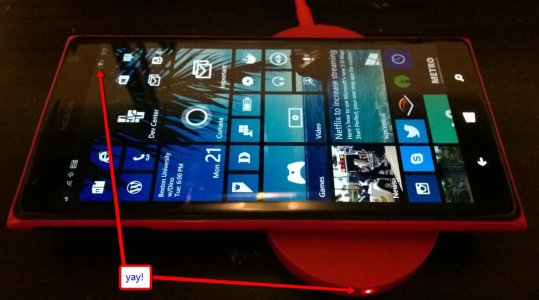
And here is the proof (I've had it on the charger for hours now. Thanks to the coil being engineered as part of the shell, it is in the right place and there is no improper heat displacement. In fact, I barely feel any heat). :cool:

WPCentralSix.jpg
 
Last edited:

hasasimo

New member
Apr 8, 2012
1,922
0
0
Visit site
Dude... awesome. Though I'm ordering one with Qi built-in, I'd feel a lot more accomplished (read: badass lol) doing it this way. Nice!
 

Benny1434

New member
Sep 13, 2012
11
0
0
Visit site
Nice! One question, what about just fliping the charging coil on the new shell so that its connections to the board (from the 925 shell) are at the bottom. Then have the boards 3 connections contact the end of the flex cable (which has the contacts)?

It looks as though it would line up pretty much spot on by just flipping the coil (guessing it is just held on by tape like the 925 coil?). Would keep soldering to the minimum by just having to connect the board, if that would in fact work.
 

myrandex

New member
Aug 20, 2009
63
0
0
Visit site
Excellent work!!!

The next question...how much would you take from someone to do this for them? :) I do not have the confidence in my skills to do this.

​Jason
 

boscoosco

New member
Apr 21, 2014
5
0
0
Visit site
I give up trying to add the 920 coil without opening the phone. I've tried aluminum foil, coiling the cables around a staple to make them tiny enough to stick into that port, shoving the cable in as tight as it would... Nothing seems to work. The last option I can think of is paying $50 for that case and gutting it and redoing it with the 920 coil. And if I mess up I'm out $50 :( There has to be a better way.

If I did go inside the phone, is there somewhere I can go to buy a rear case that has all the same stuff as my current phone has? I could modify it, make sure it's happy with life, and then just swap backs? That way I can put it back to "factory" if I ever need to return the phone to my company or whatever?
 

sadude69

New member
Dec 10, 2012
30
0
0
Visit site
Nice! One question, what about just fliping the charging coil on the new shell so that its connections to the board (from the 925 shell) are at the bottom. Then have the boards 3 connections contact the end of the flex cable (which has the contacts)?

It looks as though it would line up pretty much spot on by just flipping the coil (guessing it is just held on by tape like the 925 coil?). Would keep soldering to the minimum by just having to connect the board, if that would in fact work.

I may have missed this but don't the Lumia 925 and Att 1520 both have 3 pins? Can't you just line those up and make it work?

Also rather than take apart the 925 charging coil, just replace that full piece into the international case of the 1520 and match pins...

I think this solution is great for its use of OEM parts but if we can some how just have it non-solder it would be ideal
 

Lanceloni

New member
Nov 13, 2012
15
0
0
Visit site
The problem with going that route (I did explore all the options with layout) is there is only so much clearance you have between the motherboard components and your work. It is just a coincidence that the best place to put the PCB lined up with the new shell's charging coil.

What I will do the next time I have the opportunity to do this again, is cut the PMA flex cable a little higher up and bride the connections up there. I wanted to play it safe in case this sisnt work, I would still have an intact PMX flex cable.
 

sadude69

New member
Dec 10, 2012
30
0
0
Visit site
What I will do the next time I have the opportunity to do this again, is cut the PMA flex cable a little higher up and bride the connections up there. I wanted to play it safe in case this sisnt work, I would still have an intact PMX flex cable.

Funny you mention that as I was looking at your pics, I was like what does the rest of that PMA flex have to do....why couldn't he just cut it short like the original cable that was in the international case. I guess once we find the PMA flex cable replacement part, I have a feeling it will be even cleaner.

Just out of curiosity, is there a cheaper PCB like from the 1020 wireless shell or any other lumia phone?
 

Lanceloni

New member
Nov 13, 2012
15
0
0
Visit site
I may have missed this but don't the Lumia 925 and Att 1520 both have 3 pins? Can't you just line those up and make it work?

You cannot match the pins up because there is a different wiring configuration between the PMA and the Qi models. The important thing to remember is that there is a big difference between the ATT 1520's motherboard and the international Qi one. You need to work around this by grounding out the communication pin (the part where you see me add liquid nickel).
 

myrandex

New member
Aug 20, 2009
63
0
0
Visit site
I may have missed this but don't the Lumia 925 and Att 1520 both have 3 pins? Can't you just line those up and make it work?

Also rather than take apart the 925 charging coil, just replace that full piece into the international case of the 1520 and match pins...

I think this solution is great for its use of OEM parts but if we can some how just have it non-solder it would be ideal

I think I asked this earlier and Sonartech answered saying that the internals won't allow for that. I found a guide for the 925 that was quite nice where the Qi circuitry was removed from a 925 charging shell and integrated inside of the phone using those pins so no soldering was required. I posted a link to it hoping something like that could be done here but it didn't seem to be an option. I do want Qi and I'me ready to pay someone to do my 1520 up all nice as I don't have the skills or equipment to do so. I considered buying some equipment and practicing soldering on some old PC equipment first, as it has been nearly 10 years since I used a soldering iron, but I really would rather not risk messing up my brand new 1520. Plus I'm not even using the 1520 yet due to a stupid design flaw with WP8 that has essentially left the phone usuable for me for while I'm employed with my current employer, so if I can give up the device for some time without suffering any personal setbacks on being without a phone (still using my 920 which is in perfect condition too, and am enjoying the built in Qi charging in that device every day).

​Jason
 

cporta

New member
Oct 31, 2012
19
0
0
Visit site
I was all set to do this mod but I could not get the darn back plate off. I got the screw out no problem but I couldn't pry of the back. Can someone please give me some pointers or a video or something? I must be missing something.
 

Dono Newcomb

New member
May 8, 2014
101
0
0
Visit site
Forgive me if this has been addressed, 8 pages of thread is more reading than I have time for and I only got through 3 or so pages. But I see a solution has been found, however this would void any warranty because cracking the case and tampering with wiring and soldering ect ect. But from what I gather it appears that you are merely adding the qi by soldering it inline to the existing ribbon cable right? Can't the same resulting connection be achieved by re-routing those connections to the exterior of the shell using the provided pin slots by adding the coil to the guts of an incipio charging cover, carefully attach it to the "exterior" of the 1520 and the use whatever cover you want to protect the whole deal, and make the phone able to use both charging platforms?

I would much rather destroy or void the warranty on an incipio cover than mess with my phone's warranty if I can achieve the same results. Plus I really like my current protective cover and refuse to use the incipio, much less bow down to AT&T and let them ruin my Windows phone experience, lol.

Besides having a dual platform would be cool.
 
Last edited:

Members online

Forum statistics

Threads
326,597
Messages
2,248,613
Members
428,521
Latest member
BarkerJarrod