Qi Charging on a LUMIA 1520 AT&T phone (Solution)

I am a recent iPhone to WP convert and love my Lumia 1520! Great build quality! I am anxious to mod it for wireless charging and I am nervous to even take it apart. I have taken apart several iPhones but this unibody is a lot different and I don't want to mess it up. Will taking it apart cause it to stretch or break any clips that might make it not fit back together as well? I just want to keep my Lumia looking beautiful! I appreciate all the contributions to this thread, it helps a lot!

Also, do I need the frame shown in the teardown video to take it apart? Or will the suction cup and pry tool method be fine?
 
... <snip> ...
Update2: Took my 1520 apart this morning and discovered that the +7Vdc solder joint on the flex cable was a tiny bit high. It had pushed through my tape and was touching a metal cover just below the contact pins. I removed a little solder and reinsulated everything. Put my 1520 back together and all is well again.

Glad to hear you figured it out. For troubleshooting purposes, please know that the 920 Qi coil will/should develop a voltage with or without being attached to anything (it's completely self-contained). If the Qi charger lights flash, it generally means the coil was able to negotiate a link, but was unable to develop a load. Depending on who makes the charger, however, the behavior could vary. On some charger, "blink blink" means that the coil is detected, just not centered well above the transmitter. Unfortunately, the 920 coil is smaller than the native 1520 Qi coil, but provides the same amount of current as the larger coil. It just makes it a tad bit more difficult to align it on certain chargers. My recommendation is to locate a 3-coil Qi charger; these work very well for larger devices.

SonarTech
 
I am a recent iPhone to WP convert and love my Lumia 1520! Great build quality! I am anxious to mod it for wireless charging and I am nervous to even take it apart. I have taken apart several iPhones but this unibody is a lot different and I don't want to mess it up. Will taking it apart cause it to stretch or break any clips that might make it not fit back together as well? I just want to keep my Lumia looking beautiful! I appreciate all the contributions to this thread, it helps a lot!

Also, do I need the frame shown in the teardown video to take it apart? Or will the suction cup and pry tool method be fine?

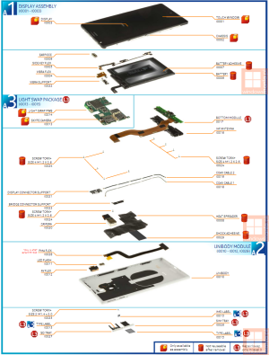
I've never needed a suction cup or the frame. These devices are WAY easier to take apart than Apple's adhesive-loaded fruit phones. I use a guitar pick and my finger nail, and I've taken apart about 15 of these things at this point. Just make sure to watch the tear-down videos so you know where to pry based on how that frame is built, and DON'T FORGET TO TAKE BOTH TRAYS OUT!! :-)

My Qi mod's still working great. I charge every 2 days and have seen no problems with the modification whatsoever.

SonarTech
 
Hey Sonartech. I have been trying to take apart my 1520. Unfortunately, I read the post that said to use a t3 torx but it ended up stripping the locking screw. I later read to use a t2 but now it is completely useless. Do you have any recommendations for removing this stripped screw without destroying my device. Thanks again.
 
I've never needed a suction cup or the frame. These devices are WAY easier to take apart than Apple's adhesive-loaded fruit phones. I use a guitar pick and my finger nail, and I've taken apart about 15 of these things at this point. Just make sure to watch the tear-down videos so you know where to pry based on how that frame is built, and DON'T FORGET TO TAKE BOTH TRAYS OUT!! :-)

My Qi mod's still working great. I charge every 2 days and have seen no problems with the modification whatsoever.

SonarTech

Awesome, thanks for the advice and info!!
 
Hey Sonartech. I have been trying to take apart my 1520. Unfortunately, I read the post that said to use a t3 torx but it ended up stripping the locking screw. I later read to use a t2 but now it is completely useless. Do you have any recommendations for removing this stripped screw without destroying my device. Thanks again.

Depending on how bad it stripped, you might be able to use a 1.2mm flat head. The other option is to use a Dremel to carefully cut a slot on each side of the screw, then use a larger flat head to just unscrew it. Finally, if you have some super-fine dykes, you can use them to either grab on to the screw to turn it, or maybe to cut slots in either side of the screw for removal.

Good luck!

SonarTech
 
So the screw on the 1520 isn't a T3 size? (I realize that if it IS a T3 size, the T2 driver should be able to work with the screw, albeit loosely.)
 
It's officially labeled as a Torx+ Size M1.4x2.0. On my Whia drivers, a T2 fits best, but at this tiny size, some have reported T3's work better.

image_windowsmania_pl.png

SonarTech
 
Unless the full LCD assemblies drop under $100, I'll be selling my shell and any components, so keep an eye out in the seller section lol I was really looking forward to doing this to my 1520.
 
Hi Sonartech,

Thanks a lot for this detailed guide! For someone that will get the flip cover with the phone(me in about 4-5 months), do you think it's easier for people to just put the 920 Qi Coil between the phone and the case, and connect the coil to the contact points? I mean, the flex between external and internal contact points for PMA doesn't have magic in there, so as long as we can short negative and trigger-negative somewhere we should be set? this way we don't have to open the phone and void warranty. what's your opinion on that?
 
...do you think it's easier for people to just put the 920 Qi Coil between the phone and the case, and connect the coil to the contact points? I mean, the flex between external and internal contact points for PMA doesn't have magic in there, so as long as we can short negative and trigger-negative somewhere we should be set?

You're absolutely correct - you could place the coil external to the phone and connect-the-dots (hehehe). Using this interface would be virtually undetectable should warranty service by required. The center dot is V+, and both dots on either side should be connected to GND.

SonarTech
 
Yet another serving suggestion for those attempting this modification...

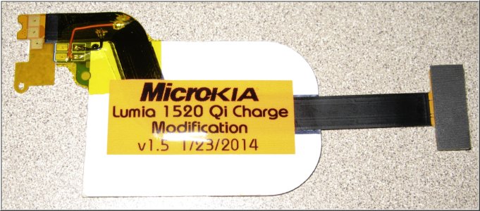
Since I installed the original mod outlined in this thread, I've had more charger placement issues than I expected. The 1520 is heavy enough that it would tilt off the small Qi charging pads, moving it just out of wireless charging range. It was a bit of a silly balancing act trying to get it to maintain a link. As a result, I re-designed the modification to move the coil further up toward the center, and now the alignment process seems much simpler (and balanced). Here's what it looks like for those interested:

V1-5Full.jpg

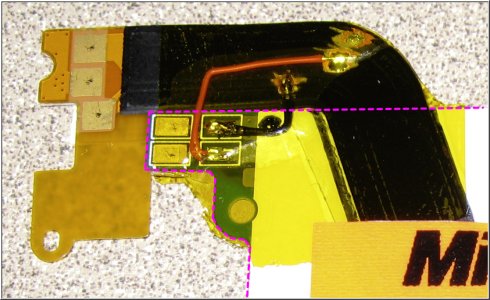
Here's a close-up of the critical area:

V1-5Close.jpg

The pink dashed line shows the periphery of the 920 Qi charging coil PCB and where I moved it in relation to the PMA flex. I moved the top contact pad almost flush with the PMA flex connection to the main board. This places the charging coil almost dead-center inside the 1520. This also makes the 1520 much easier to balance at center on top of a charging coil. Having it sit "somewhere" in the lower half of the device was tedious. Having it centered seems more natural. Just don't place it too high, so that the PCB and the flex overlap...

So far, it's sitting quite happily on top of my original Nokia charger. No changes to the wiring, so don't place too much stock in the extra scraped-off area visible in my pictures; I just recycled the original flex I used from my first modification.

Keep Calm and Charge On.

SonarTech
 
Sonartech: You are amazing. Thank you for contributing your findings for everyone!

I'm happy to report that the little screwdriver kit with a t2 "bit" (it's more like a plug-in driver) works perfectly with my phone's screw. Now I just need to find a local retailer who carries 22 or 24 awg core bus cable.

Would you also recommend one of those "helping hands" magnifying lenses that you can buy at RadioShack and the like to help with the scraping of the flex and subsequent soldering?
 
Thanks for the kind words. The 'helping hands' are probably not a bad idea, given the nature of this modification. There are two fairly tedious bits associated with this modification:

  1. Scraping the mask off the Mylar flex without hacking into (or through) the actual copper trace. Gentle hands are required, and you only have 1 PMA flex, so you have to get this part right, or you'll have to repair the damage you did to the flex (yuk!). Trying to scrape off the solder mask and shielding on the flex should definitely be done under decent light and good magnification - with a healthy amount of patience.
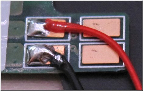
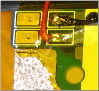
  2. Soldering the bus wire to the 920 Qi coil PCB. The OEM 920 Qi coil comes with gold contact plates pre-soldered to the PCB. These Ɓitches move around all over the place the instant they get hot, so unless you're holding them down to the PCB (along with the bus wire you're trying to solder in top of them), chances are pretty good these contact plates will %@#$ you somehow. Depending on your skill and your patience, you might just want to remove the gold plates entirely and solder to the 4 pads underneath instead. Here's what it looks like:

WithPlates.jpg
Figure 1: Close-up of PITA gold contact plates. Enlarged to show texture... :winktongue:

WithoutPlates.jpg
Figure 2: A crappy close-up showing the 4 pads hiding under the gold plates.

There's no real benefit to having the gold plates in place. Technically, they just add another layer of thickness (and frustration), so I'd probably recommend they be de-soldered and removed prior to attempting to solder the bus wire to the pads. You don't need to contact all 4 pads with the bus wire, either - two or three is fine, so long as you end up with a nice shiny, low-profile and physically secure connection. Stay at or under 650?F on these pads, and dwell no longer than about 5 seconds per pad or you risk lifting the trace off the PCB. Be sure to pre-strip and tin your bus wire, too, so all you have to do is drop it in place and heat the joint to make the connection.

Again, good luck!

SonarTech
 
Thinking about removing the strip from my 820 shell and adding it to a 1520 case. I don't care that it is in an external case as I need a case anyway. The only thing that bothers me about the PMA, other than getting another charging pad, is that I can only seem to find one case and it is fat and black. If anyone has done this with a case instead of internal, please let me know how it turned out.
 
The only disassembly video for the 1520 that I could find is, in a word, useless. It requires the use of a frame that isn't commercially available (as far as I know). I attempted to use a thin plastic tool to gently remove the unibody from the case without luck. It felt too much like I would bend, break or at least overly compress the external material of the unibody too much. I knew that this would not be a simple task but when step 1 is this much trouble, I find myself wanting to go through with it a lot less. :(
 

Forum statistics

Threads
332,314
Messages
2,255,301
Members
428,700
Latest member
kellettwendy8