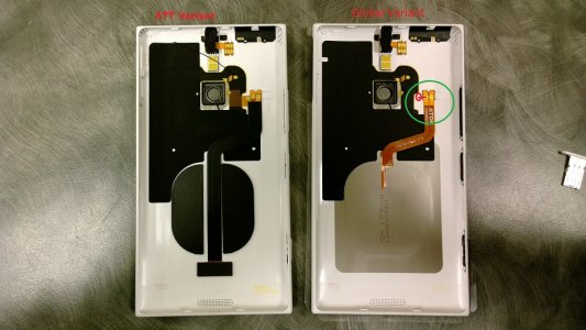
Qi Charging on a LUMIA 1520 AT&T phone (Solution)

Sonartech

New member
Dec 17, 2013
43
0
0
Visit site
At what rate does this charge?

This is somewhat ambiguous, since wireless charging isn't a direct-connect technology. Ideal coupling will result in 600 - 675mA received current at about 6.4vdc. Additionally, the 1520 will only pull 700mA from the PMA wireless charging connection, as tested at 5 to 7.5vdc.
 

Sonartech

New member
Dec 17, 2013
43
0
0
Visit site
Maybe as soon as we find a source for the PMA flex cables. Unfortunately, 2-way mail isn't feasible for me due to the nature of my employment, so you'll have to make the mods yourself or buddy-up to someone with the hardware and the necessary skills.
 

ceroberts75

New member
Jan 4, 2014
8
0
0
Visit site
if you just need to connect the -T to the -, with the global variant case, wouldnt it just be easier to just somehow add an extension to the - connecting it to the -T on the Qi flex cable?

would it work?

WP_20140102_19_23_05_Pro.jpg
 
Last edited:

Sonartech

New member
Dec 17, 2013
43
0
0
Visit site
I'm not sure I fully understand your question. The International 1520 case only comes with a 2 conductor flex and an Qi antenna that can't be used for anything. It's missing a required (Trigger -) conductor and the required Qi electronics necessary to generate DC current from the AC signal - that's why you need a 920 Qi-coil. The International 1520 case is essentially useless for this modification. About the only thing it would be good for would be to eliminate the 3 PMA conductive charging dots on the back of the shell.

SonarTech
 

ceroberts75

New member
Jan 4, 2014
8
0
0
Visit site
the global still has a +/- right?

my understanding or the -T is that is works like a remote (blue) wire on a radio where that is what triggers the amps to power on, or the power to start to the antanna.

I am not sure if this is doable, but this thread is very interesting and guessing that the global cable contacts are in the order, left to right, -, +, then since we are in essence shorting the connection on the board of the ATT by connecting the -T & -, wouldn't it be the same as some how jumping/connecting the - on the global variant to the missing area with a small plate that can connect the two from the motherboard?
 

ceroberts75

New member
Jan 4, 2014
8
0
0
Visit site
as it stands, just changing the case alone, allows the charge to light, but not hold. so wouldn't that mean that the charging device is connecting, but not reciprocating the handshake because the motherboard is not accepting the charge and could be saying that the batter is full for a failure of completing the connection?
 

Sonartech

New member
Dec 17, 2013
43
0
0
Visit site
the global still has a +/- right?

my understanding or the -T is that is works like a remote (blue) wire on a radio where that is what triggers the amps to power on, or the power to start to the antanna.

I am not sure if this is doable, but this thread is very interesting and guessing that the global cable contacts are in the order, left to right, -, +, then since we are in essence shorting the connection on the board of the ATT by connecting the -T & -, wouldn't it be the same as some how jumping/connecting the - on the global variant to the missing area with a small plate that can connect the two from the motherboard?

No, the Global 1520 doesn't have +/-, it's an AC input, not a DC input. The Qi antenna provided in the global 1520 doesn't have any integrated electronics to provide DC conversion - that is normally done on-board by the 1520 itself. The electronics that handle Qi power negotiation and provide HF AC to DC conversion are not installed in the AT&T 1520 variant - the pads are not even populated (at least not in my 1520's).

Simply adding an HF AC coupling antenna won't work; the PMA inputs are designed to support PMA chargers that provide 5v nominal DC voltage. It just happens to be tolerant of the 7vdc that a Qi coil provides because the input to the PMIC was designed to support either standard. The PMIC doesn't care what provides the current (Qi or PMA). In the AT&T device, there is no AC to DC conversion for the Qi antenna, and we're working around that by using a self-contained Qi circuit (the Lumia 920 Qi circuit) that provides direct DC voltage, same as the PMA charger would. All you're doing is coupling HF AC to an input designed to use DC current.

So, unless you have another variant of the 1520 that accepts either AC or DC at those inputs, then I don't believe this could work. That said, I must admit I didn't try this exact scenario, because the trigger circuit expects a ground to trigger the charge input, not an AC signal from a Qi coil, so I didn't see the point. Feel free to experiment on your device, but I'd think twice before feeding direct HF AC current into the PMIC. :unhappysweat:
 

Sonartech

New member
Dec 17, 2013
43
0
0
Visit site
as it stands, just changing the case alone, allows the charge to light, but not hold. so wouldn't that mean that the charging device is connecting, but not reciprocating the handshake because the motherboard is not accepting the charge and could be saying that the batter is full for a failure of completing the connection?

WHAT?! Really? This was the VERY first experiment I tried during my investigation, and I never got so much as a peep out of my 1520 by just adding the Qi coil. Are you absolutely certain of this?

Can anyone else corroborate this? If so, this implies there might be a 2rd AT&T 1520 variant out there that has on-board Qi support populated, but has been altered in some other way to work with PMA. (?????)

I've modified 4 of these devices so far, and they're all identical.
 

Benny Vallejo

New member
Sep 28, 2013
78
0
0
Visit site
WHAT?! Really? This was the VERY first experiment I tried during my investigation, and I never got so much as a peep out of my 1520 by just adding the Qi coil. Are you absolutely certain of this?

Can anyone else corroborate this? If so, this implies there might be a 2rd AT&T 1520 variant out there that has on-board Qi support populated, but has been altered in some other way to work with PMA. (?????)

I've modified 4 of these devices so far, and they're all identical.

If this does end up being the case Sonartech...what do you think can be done? A mod with the global variant maybe? I am sure you are very thorough but maybe the contacts weren't hitting correctly maybe? I am still waiting for my global back cover to ship in but i will try this as well when it comes in.
 

peacock93

New member
Dec 14, 2011
139
0
0
Visit site
Sonartech is correct on this. There is no AC to DC converter in the AT&T 1520. That is why the PMA charging cover I disassembled had all the electronics, HF AC coil plus AC to DC converter, built in to it.

I'm not saying that a mod to the International case won't work but your still going to need the 920 coil and circuit board assembly. That is why I've been trying to find a source for the AT&T 1520 PMA flex cable. I then could mod my International case and keep my AT&T case for warranty replacement if necessary.

Once I get my 920 coil and International case I'll see if there is any reliable way to mod it without the PMA flex cable. My hopes are not very high on this.
 

ceroberts75

New member
Jan 4, 2014
8
0
0
Visit site
Yes. I don't think enough current gets through to start a charge, but the charging plate light will blink on/off if placed correctly.

Just not sure if that meant anything.

Great creativity in your solutions btw.
 

darth_furious

New member
Oct 30, 2012
82
0
0
Visit site
I have the same problem. The lights blink. I tried so many times to get it to work and I gave up.
Strange thing is that I took an old 5v charger, cut the tip and connected the wires to the 3 pins outside with some paper clips and it charges. I can't get the qi coil to work with the phone. I can get the qi coil in the case and put a car dashlight bulb on it and light it up through qi powering it no problem. I confirm every contact on the flex is soldered correctly through the bulb. I put the case on and put back on charger and it blinks. Works fine when case is not attached to phone. I put too many hours and I give up
Sent from my nokia 1520 using Board Express
 

Sonartech

New member
Dec 17, 2013
43
0
0
Visit site
Oh, I understand - you're talking about the indicator on the charger, not the 1520 itself. I was under the impression that the device itself charging charging for an instant, then stopped. So, just to confirm, none of you have ever seen the 1520 itself start a charge, then stop, from just having the Qi coil (with no electronics) installed, correct?

There is a recurrent HF AC chirp that starts the process (i.e., the "selection" phase). This is commonly referred to as an "analog ping". During this period, the presence of a receiver is detected (a load of "some sort"). If the Power Transmitter discovers a Power Receiver, the Power Transmitter may extend the Digital Ping, i.e. maintain the Power Signal at the level of the Digital Ping. This causes the system to proceed to the identification & configuration phase. If the Power Transmitter does not extend the Digital Ping, the system shall revert to the initial selection (object detection) phase. During the identification and configuration phase, the Power Transmitter identifies the selected Power Receiver, and obtains configuration information such as the maximum amount of power that the Power Receiver intends to provide at its output. The Power Transmitter uses this information to create a Power Transfer Contract. This Power Transfer Contract contains limits for several parameters that characterize the power transfer in the power transfer phase. At any time before proceeding to the power transfer phase, the Power Transmitter may decide to terminate the extended Digital Ping, e.g. to discover additional Power Receivers. This reverts the system to the selection phase. In the power transfer phase, the Power Transmitter continues to provide power to the Power Receiver, adjusting its Primary Cell (coil) current in response to control data that it receives from the Power Receiver. Throughout this phase, the Power Transmitter monitors the parameters that are contained in the Power Transfer Contract. A violation of any of the stated limits on any of those parameters causes the Power Transmitter to abort the power transfer, returning the system to the selection phase. Finally, the system may also leave the power transfer phase on request of the Power Receiver. For example, the Power Receiver can request to terminate the power transfer, i.e., "battery fully charged", reverting the system to the selection phase, or request to renegotiate the Power Transfer Contract: change to trickle charging the battery using a lower maximum amount of power, reverting the system to the identification & configuration phase. These control packets are sent approximately every 250 ms during normal operation or every 32 ms during large signal changes (i.e., you move the coil). Also during normal operation, the power transmitter sends power packets every 5 seconds. The power transmitter stops supplying power upon receiving an “End Power” message, or if no packets are received for more than 1.25 seconds and the process repeats. While no power is being transmitted, the power transmitter enters a low-power standby mode, but remains active.

The presence of a Qi inductive coil only satisfies the very first part of the start-up sequence. It's possible that the charger's designed to turn on its indicator after an initial analog detection, or any time the transmitter is not in a low-power state. If that's the case, that could explain why the light on the charger blinks with just a coil present (no electronics). However, I would expect it to repeatedly blink every 1.25 seconds (or faster, since no communications are actually taking place between the "dead" coil and the power transmitter.

As for the "dashlight bulb" blinking - I was a little freaked-out by that until I realized you must be using a self-contained Qi coil circuit (i.e., from a Lumia 920), not just the Qi coil by itself. If not, and you had a charging plate that was inducing enough of a charge to light a bulb with JUST the coil attached, you'd essentially have an induction cook-top, not a cell phone charger.

Still, this is starting to get awfully deep. While I would love to hope that the Qi electronics survived AT&T's meddling, I've seen the two boards side-by-side, and I'm certain that the AT&T units I've looked at do not have Qi detection, negotiation or rectification electronics installed in them to support the coil-only scenario.

SonarTech
 
Last edited:

cporta

New member
Oct 31, 2012
19
0
0
Visit site
Well, I ordered my 920 coil from etrade supply. I'm determined to do this.

Sonar, can the bottom 3 external pins be cut from the flex cable? I think I might use my global back cover. Also is there any reason I couldn't use solder with flux already on it?
 

Sonartech

New member
Dec 17, 2013
43
0
0
Visit site
Well, I ordered my 920 coil from etrade supply. I'm determined to do this.

Sonar, can the bottom 3 external pins be cut from the flex cable? I think I might use my global back cover. Also is there any reason I couldn't use solder with flux already on it?

Sure, you could cut the contact dots off the flex. Just make sure you insulate the cut edge of the flex with a small amount of Kapton tape (or equivalent). Not sure what you mean by "the flux already on it", however. There's no flux anywhere on that flex unless you put it there ;-) Or wait, did you mean "solder with flux already in it?" Rosin-core solder works fine. 63/37 or RoHS... there's no OSHA inside your phone to care if you use leaded solder.
 
Last edited:

Members online

Forum statistics

Threads
326,569
Messages
2,248,577
Members
428,515
Latest member
crousetored