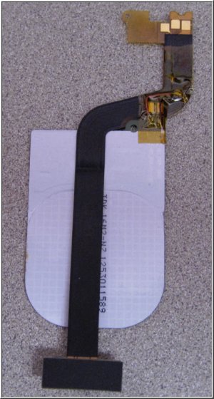
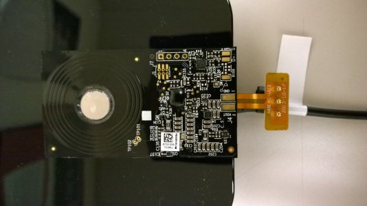
Qi Charging on a LUMIA 1520 AT&T phone (Solution)

Sonartech

New member
Dec 17, 2013
43
0
0
Visit site
The left 2 pins are together in one black plastic unit and the right one is encased in it's own black plastic. The left and center pins are power definitely and I have confirmed by applying a charge. The right one must be a communication pin

Correct. The left 2 pins are the only pins populated on the PCB for Qi-style wireless charging and connect directly to the coil antenna. The right-most third pin appears to be only associated with PMA-based charging. The PCB's between an international 1520 and the AT&T version appear identical, with the exception of which parts get populated. The pads for that third pin are still present on the International 1520, they just aren't populated with electronics.
 

peacock93

New member
Dec 14, 2011
139
0
0
Visit site
Just got a Incipio PMA cover and Duracell PowerMat. First off what a huge and ugly cover!! No way even close, in size or looks, to my wife's 1020 Nokia charging cover. Also it is very picky on placement even though it is magnetized.

I tested the cover voltage and resistance and here's what I found.

Looking at the inside of the cover with the camera hole at the top.

The pin on the Left is Ground/Common. The Middle is +5Vdc and the Right is Ground/Common. The Left and Right pins shows 0 Ohms between them and Open between the Left to Center and Right to Center.

I hope this helps. I also have an international shell coming so I will be doing some more testing once I receive it.

Update:

Since I'm never going to use this PMA cover I decided to take it apart.

Even though there are 3 pins there is only +5Vdc and GND. As you can see in the attached pic the 2 outside pins are connected via copper trace.

Since SonarTech has stated that the International case only has the Qi coil and no AC to DC converter then I'm not sure if the International case will work at all. I also tried the PMA coil on a Qi charging plate and only got 1Vdc and it bounced to 0Vdc a lot. I know they run at different frequencies but thought I would give it a try since I had my meter out.

Well, I guess if all else fails I can install the Incipio PMA coil into my 1520. At least I wont have that huge case attached to my beautiful phone! The Duracell charging pads are $25 on Amazon so it's not to expensive to pick a couple more up. I wish they had a stand version like Nokia's DT-910. I can always fab something up though.

Ok, this all I have for now. Maybe SonarTech or Darth can come up with something that will work with Qi with this new information.

WP_20131226_08_48_38_Pro.jpg
 
Last edited:

Sonartech

New member
Dec 17, 2013
43
0
0
Visit site
Wow, this is quite revealing and interesting. Thanks very much for supplying this data!!
So, what we learned from this is that we may be able to convert a Qi-based self-contained charger into a compatible AT&T 1520 charger after all. Only problem is that the voltages are slightly different. I know my self-contained Lumia 920 Qi-charging antenna supplies 7.xx volts DC when it fully negotiates the link between the charger and the antenna. Also, Peacock93 has supplied another piece of potentially critical info - that both outer pins are connected common as GND, and this may be the key trigger that initiates the charging process. I have only ever tried to supply voltage to either one of the GND pins, but never both at the same time. So, here's my theory: Perhaps the LDO inside the AT&T 1520 can support a range of voltage, and perhaps that includes 7.xxVDC. If so, then we might have a workable solution using a self-contained Qi Antenna (like ones found in the 920) - all we might have to do is short both outer pins. If not, then the other possibility is to find a surface mount LDO to convert the 7.xxV from the Qi-charger to the 5.0v that AT&T 1520 expects to see from the PMA antenna and solder it in place on the Qi antenna. There could still be one additional "gotcha"... Since we know AT&T partnered-up with PMA so they could throw ads at people while they charged their devices at Starbucks "for free", it's entirely possible that the PMA charger is coupling 2-wire data to the Lumia through the power pins. If that's the case, then there could be 1 more layer of PMA BS to dig through to make this work, if that data is used to "authenticate" a PMA charger before allowing it to happen... I don't think that's the case, however, so my fingers are crossed!!
 

MrUNOwen

New member
Nov 28, 2013
3
0
0
Visit site
On the topic of voltage, you can get a qi adapter for the note 3 which supplies 5v and just solder the wires as needed. I tried to create my own connector to touch those 3 contacts, but that hasn't been reliable. Has anyone's order of that replacement cover come in yet? I'm tempted to use the one provided if possible, or just expose those connectors and wire my galaxy note 3 adapter to those connectors.

When anyone does get their adapter, please let me know what the voltage is. Also for those electrical engineers specialising in batteries and charging circuits. Does an extra 2v pose a risk on a 5v line? I'm wondering if it would be better as a higher voltage generally increases the rate of charge for a battery.
 

bsd107

New member
Oct 31, 2012
93
0
0
Visit site
<rant>
I too wonder if the LTE compatibility was worth losing both Qi charging and 16GB of memory. I seriously do question my decision now.
</rant>

In addition to giving up LTE compatibility, you are also almost certainly giving up Internet Sharing capability on AT&T if you get the international version. Even on AT&T hardware, slight changes to software break the Internet Sharing compatibility on other Lumia devices. And I'm not talking about trying to get "free" Internet Sharing - I'm talking about paying for the service, but having the phone not recognize that you have that service activated with AT&T unless it is a genuine AT&T Lumia device with AT&T issues firmware.
 

Sonartech

New member
Dec 17, 2013
43
0
0
Visit site
Looks like I have a viable solution. :smile: It's definitely a hack, but if you have the means and you really want it, it IS possible to add Qi charging to the AT&T 1520, no thanks to AT&T (may they burn in hell).

BEHOLD, THE FIRST (?) AT&T 1520 Qi-COMPATIBLE CHARGER MODIFICATION...
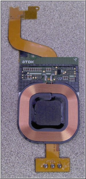


IMG1.jpg IMG2.jpg

The information that Peacock93 provided about the PMA charger was absolutely instrumental in making this work, so my hat's off to him for dissecting his newly purchased Incipio charging cover.

The three things we needed to establish was Polarity, Trigger and Voltage tolerance. Peacock93 provided the polarity, trigger and part of the voltage tolerance (5v). The only other bit that needed to be solved was voltage tolerance, since the self-contained Qi charging element provides 7vdc instead of 5vdc normally supplied by the PMA charger. Also, I wanted a modification that was removable and didn't require a permanent modification to the phone hardware. The only associated risk I had to take was establishing if a 7v Qi charging element could drive the same input the PMA charging element supplies without damage to the wireless charging circuit. +5v was applied to the the center "dot" on the back of the 1520, and GND was applied to both outer "dots". Charging began immediately at 700mA. The voltage was increased to 6v, and still the current draw was 700mA. 7v still pulled only 700mA, and I stopped at 7.5v which also still only pulled 700mA. This tells me that Nokia likely used the same electronics for the input to the actual charger, whether or not current is supplied by Qi or PMA. I would have done the same as a hardware designer, so that makes sense. Once I found that 7v seemed "safe", the next step was to find a semi-elegant way to add the coil to the flex and get everything installed.

This modification takes a self-contained Qi Charging Element and puts the output of that charging element on the same flex used by the ever-so-worthless PMA charger.

Once the modification was installed, the battery app tells me that my device is charging at a rate of 12.67% per hour, which is about what I'd expect. A hardware charge via USB from a 1.0A wall charger results in a charge rate of 14.02% per hour, so this confirmed that my coil was in fact being loaded by about 700mA by the device, and this seems to be about as good as it gets. My original tests at 5, 6 and 7 volts were current-limited to 1.25 Amps, and I never saw any demand above 702mA.

Disclaimer
This is a hardware hack. It WILL void your warranty. You risk irreparably damaging your 1520. If you attempt to do this work, you do so entirely at your own risk, with only yourself to blame if things go South. It is up to you to verify the validity of these instructions prior to permanently installing this modification into your device.

Requirements

Step 1: Carefully remove the Qi charging electronics from whatever charging cover you purchased. Try not to crack the ferrite shielding around the periphery of the coil as this significantly aids in getting a good inductive link between the coil and the charger.

Step 2: Verify your Qi charging element actually works stand-alone, on a Qi-enabled charger. You will have to determine which pins on your particular charging coil are the output. If you see 5 to 7v being supplied by your charging coil when it's sitting on the charger by itself, you're ready to proceed. Mark (+) and (-) on your charging coil output and double-check this to make absolutely certain it is correct. It would be best if you could load-test the output to verify you're using the correct pins, but as a rule-of-thumb, the larger the traces are leading to the output pads, the more likely it is that you've found the correct pads. Small, thin traces are usually only used for low-voltage signalling. Be sure you get the polarity marked right!! If you get the polarity backwards and you install the mod without testing, you will get no second chance as you will probably destroy the trigger transistor on the 1520 that initiates the charging process. So sorry for your loss...

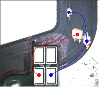
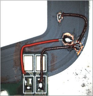
Step 3: This step gets a little abstract depending on how your particular Qi charging coil is configured, so I'll show you what I did, and you can adapt this step to fit your particular coil. What you need to do is scrape the black mylar mask off the PMA flex as shown below, solder a jumper as shown to short the two outer-most charging "dots", arrange your coil so that it sits in the appropriate place, then solder the output of your charging coil to the exposed copper on the flex so that the voltage can pass from the coil into the flex. Easy, huh?!?! Here's some illustrated pictures I took to help you:
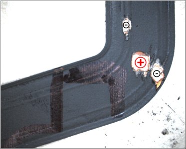
Flex1.jpg
Use a sharp but blunt tool to genty scrape away the black mask and mylar coating on the flex as shown above.
• Be extremely careful not scrape away adjacent traces to prevent shorting •
You'll know when you've mined out enough mylar when you get to bright, shiny and fresh golden copper. Copper is NOT silver, so keep scraping if you run into something that looks silver-ish. It's just a metallic paint used for shielding.
Flex2.jpg
This picture shows the output tab of my Qi Charging circuit (Lumia 920). The top two terminals are for signalling and are not required for use. The bottom two terminals are 7v primary output, left positive, right negative. Note the size of the traces at the very bottom edge of the picture that gives you some indication of which traces are the primary output from the coil - see how they are much wider than the top two thinner signal traces.
The black marker seen on the flex is where I needed to position my coil so that it was in the right area in my 1520. This coil position is determined by where the PMA flex normally sits in the back cover, so keep that in mind when planning your placement and soldering.
WARNING: AVOID LONG WIRES when connecting the coil to the PMA flex and keep your soldering as low-profile as possible! No BLOBS! Use Flux!
Flex3.jpg
This photo shows my completed soldering. Ugly you say? F-You! It's magnified 25x for your viewing pleasure(s)!

Step 4: Once you have completed the flex modification, de-flux your flex (I've always wanted to say that), clean everything up, then test the coil on your charger, and verify you didn't %^$* anything up. Use the Multi-meter and measure the voltage at the dots on the flex - verify that the middle dot is +7v, and that BOTH outer dots are connected to negative. If they are, you're ready to proceed, and you should have something resembling this monstrosity:

IMG1.jpg

Step 5: Remove the 2 rubber spacers installed in the cover that sit on either side of the PMA flex. These eat up the space that would normally be used for the proper 1520 Qi charger coil if AT&T weren't such a bunch of pricks. Did I say that aloud? Oh, sorry, that was supposed to be my 'inside voice'...

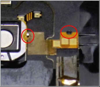
Step 6: Position the modified flex into the 1520, and snap the gold dots back into their original holes in the back cover. You may have to use more force than you think. Use the picture below as a guide for replacing the top end of the modified flex back in place:
Alignment.jpg

Step 7: Use Kapton tape to cover any exposed solder points/wires/connections on the flex, then use Kaptop tape to hold the coil to the PMA flex and back cover to keep it from moving around.

Step 8: Re-assemble your 1520. Before screwing it shut, however, power on your device and try out the Qi charging. Verify that it works as expected. If it does, finish assembling your device and you're done! Post your results along with details on whatever coil you used, since I did a crappy job of explaining that part.

Good luck, and don't sue me if you set your house (or hair) on fire.

:grin:

SonarTech
 
Last edited:

GrayW0lf

New member
Jun 7, 2012
481
0
0
Visit site
I'll have to review everything when I'm more alert. Thanks for posting your adventure into getting Qi charging to work!
 
Last edited:

peacock93

New member
Dec 14, 2011
139
0
0
Visit site
Requirements
  • AT&T 1520
  • Self-contained Qi Charging element, i.e., one from any of the Lumia's that have a Qi charging cover such as a 1020. I don't have a comprehensive list of compatible cases.
  • Solid core bus wire, 24-26 AWG
  • X-Acto Knife
  • Kapton Tape
  • Digital Multi-meter

SonarTech


Great write up and pics SonarTech!! Thank you so much! I have one question, just to make sure I get and use the same coil you did. Did you use a 1020 charging cover to get your coil? I know you mentioned it in your requirements but just double checking.
 
Last edited:

swimmer160

New member
Oct 30, 2011
56
0
0
Visit site
Sonartech, that's some legit engineering. Many, many kudos and internets to you good Sir, and to all that helped out in getting this figured out.
 

crav4speed

New member
Sep 20, 2012
408
0
0
Visit site
Or we can just wait for a Qi compatible case :smile:

Awesome work Sonartech! For anyone who's willing to try this, this is very valuable knowledge.
 

peacock93

New member
Dec 14, 2011
139
0
0
Visit site
I have an extra shell coming. So, I'm just going to modify it and save the original AT&T shell in case I ever need to send it in for warranty service.
 

Sonartech

New member
Dec 17, 2013
43
0
0
Visit site
Thanks a bunch,,
When you say Lumia 925 do you mean the phone itself or the shell of Lumia 925 ?

Sorry, I meant Lumia 920, not the 925.

In the 920, it's essentially a sticker stuck inside the interior back shell. With some heat gun McLovin', it comes out pretty cleanly. I did, however, clean the factory adhesive off with Novec prior to repurposing it for use inside my 1520. Sure was nice to wake up to a 100% charge after leaving on my Qi pad overnight. No problems with it whatsoever; no abnormal heat issues, etc... I also saw the charge jump to about 20.4% per hour, according to the Battery app.
 
Last edited:

Hemant Khatod

New member
Dec 29, 2013
5
0
0
Visit site
Thanks .

I guess I need to rephrase my question.

Are you talking about back of the PHONE -lumia 925 or are you talking about the wireless charging shell that you attach to the phone from outside for wireless charginng ?


Bottom line : Should I buy this:

http://www.etradesupply.com/nokia-lumia-925-battery-door-black.html

OR

http://www.amazon.com/Nokia-CC-3065...ag=hawk-future-20&ascsubtag=UUwpUvbUpU2277660


OR


Will something like this work:

http://www.amazon.com/Docooler-Stan...ag=hawk-future-20&ascsubtag=UUwpUvbUpU2277660

Thanks again
 
Last edited:

Sonartech

New member
Dec 17, 2013
43
0
0
Visit site
this looks awfully similar to what you have used

Nokia Lumia 920 Wireless Charging Coil

Yep, that's EXACTLY what I used; the "925" was my mistake - it was a dead 920, not a 925. I got the thing already disassembled, and I didn't actually look at the designator for it. Nokia called it a "Phi", but it's a Nokia 920, and that's the exact same coil I installed. Thanks for working that out.
 

Members online

Forum statistics

Threads
327,397
Messages
2,249,976
Members
428,641
Latest member
RomnKais