Qi Charging on a LUMIA 1520 AT&T phone (Solution)
- Thread starter Benny Vallejo
- Start date
You are using an out of date browser. It may not display this or other websites correctly.
You should upgrade or use an alternative browser.
You should upgrade or use an alternative browser.
Sonartech
New member
- Dec 17, 2013
- 43
- 0
- 0
Good job Sonartech!
Sorry for the threadjack but is nokia/at&t going to come out with a 1520 with a built in PMA charger in a few months? I'm trying to decide whether to wait or to get the current 1520 and do the Qi mod.
My understanding is that Nokia was fairly disgusted with the AT&T requirement to support PMA, especially since for them it was significantly more expensive (a cost that was undoubtedly passed on to us through AT&T); after all, Nokia did have to spin up additional lines to generate the AT&T variant which has a different BOM than the International variant. It's neither easy nor cheap to start a parallel production on a "different" version of essentially the same hardware. The LTE support is a QCN & software change, but supporting PMA instead of Qi was definitely both hardware and software. I still don't understand the insanely asinine decision by AT&T to cut 16GB of memory out of the base 1520 design, but I'm sure it's related to money somehow. Perhaps they screwed us out of 16GB of memory to offset the increase in production costs associated with building a 1520 that supports PMA instead of Qi... who knows...
That said, I would be absolutely shocked if Nokia built-in PMA into any of their designs. Supporting it through the back shell as an accessory is one thing, but actually incorporating PMA electronics into their internal hardware design is another thing entirely. I think it's more likely that you'd see Nokia come up with support for BOTH PMA and Qi in the same circuit before they'd go 100% PMA only. Just follow the PMA member's list and see if Nokia ever signs on as a member. That will be your first indication that shenanigans are about to occur in the current wireless charging war.
As for integrating PMA support in your AT&T 1520, that's pretty easy. You just have to take apart your device and insert the PMA charging coil electronics into the back cover, make the electrical connections similar to what was already shown in this thread with the Qi modification, then secure the PMA coil inside the back shell with some thin double-sided tape. The max distance for effective magnetic coupling is around 6mm, so keep things thin, and keep the coil as close to the back shell as possible (i.e., don't use that thick-aƨƨ 3M foam-style double-sided tape to hold the coil in place). Beyond that, the instructions for adding PMA internal to the AT&T 1520 is essentially the same as adding the Qi coil. They both go to the exact same places on the PMA flex.
I found a video on You Tube about doing this for a 925, and it's essentially the same process for the 1520. You can view that video here:
How to hack wireless charging into the Lumia 925 - YouTube
Cheers,
SonarTech
William Velez1
New member
- Dec 19, 2013
- 18
- 0
- 0
Hemant Khatod
New member
- Dec 29, 2013
- 5
- 0
- 0
Thanks Hemant Khatod! I have one on order now.
Grt. Let us know how it goes. I will order one too..
Sonartech
New member
- Dec 17, 2013
- 43
- 0
- 0
Hey Sonar - how about a video for the 1520?? =-)
Sorry, that's a little too close to social networking for me. I enjoy having virtually zero social footprint on the Internet (I consider Apple, Facebook and Twitter to be the root of all evil on the net today). I'm happy to take as many pictures as you need on the matter, but making a public video's going to be extremely unlikely. Once you give to the Internet, you can never take back. I will, however, probably make a better guide once my 920 coils arrive and I can refine the procedure. The first one's always the roughest, as it serves as more of a prototype / proof-of-concept than an actual procedure. Now that we know this can be done, it'll definitely get revised, refined (and probably stolen) by someone else...
Citizen X
New member
- May 11, 2013
- 524
- 0
- 0
I still don't understand the insanely asinine decision by AT&T to cut 16GB of memory out of the base 1520 design, but I'm sure it's related to money somehow. Perhaps they screwed us out of 16GB of memory to offset the increase in production costs associated with building a 1520 that supports PMA instead of Qi... who knows...
I figured they removed parts not only to support PMA but also to keep costs down. Most people in the US that have this phone probably got it for $99 on contract... or less. Electronics usually cost less in the US vs the rest of the Western World so I don't know if pricing is due to that phenomenon or because parts were removed. I don't know how the costs of setting up a whole different production line stack up to the savings from deleting parts. Personally I don't really see a scenario where 32 GB is going to change my life significantly vs 16 GB. Even with no expansion memory I am using less than 14 GB of my memory on my Lumia 900. Granted I think I offloaded a bunch of pictures at one point and I rarely shoot video. But with a 64 GB removable expansion option I would be set. I and most people don't play a lot of games. I guarantee you when a 32 GB at&t version is finally available most people will balk at the price and get the 16GB version... despite all the wailing on the internet.
That said, I would be absolutely shocked if Nokia built-in PMA into any of their designs. Supporting it through the back shell as an accessory is one thing, but actually incorporating PMA electronics into their internal hardware design is another thing entirely.
Why? What would be the roadblock? Is it a cost thing or a licensing thing?
The reason I ask is because at&t said this...
In an effort to move toward making this a reality for consumers worldwide and in direct support for the public ecosystem roll out led by Powermat, we have asked our device suppliers to integrate PMA-certified wireless charging solutions by 2014.
Does an add on shell satisfy this request? And is this a request or a requirement?
I think it's more likely that you'd see Nokia come up with support for BOTH PMA and Qi in the same circuit before they'd go 100% PMA only.
I didn't even know that was possible.
As for integrating PMA support in your AT&T 1520, that's pretty easy...
Honestly I just asked because if I could wait a few months and get a native at&t phone with some kind of built in wireless charging I would wait and get it regardless of whether it is PMA or Qi. I have no wireless charging accessories so I am indifferent between the two at this point. I worry that at&t is moving to PMA so I hesitate in getting a bunch of Qi chargers. But at the same time in two years at&t may move on to A4WP or switch back to Qi. I'm really just taking the path of least resistance. Your Qi hack looks like the easiest actual solution at the moment. I'm still on contract so I can wait a couple of months.
lucas.scott
New member
- Mar 11, 2012
- 212
- 0
- 0
Has anyone removed their shell yet? What tools did you use? I have replaced many screens and have a plethora of screw drivers that came with my replacement parts. Unfortunately , they all seem to be too large for the small hole that the 1520 has.
Also - what did you use to separate shell from LCD? In the teardown video they appear to have a frame made specifically for 1520, but I have not seen any of those anywhere. Use the old suction cup method perhaps?
I am actually glad to make a video documenting the process.. I just need to know what tools to order
tonybessette
New member
- Dec 30, 2013
- 60
- 0
- 0
Fortunately I bought mine from a Microsoft store with the Protection plan so if I break it I'm covered.
How much does this protection plan cost? I'm going to the Microsoft Store in Orlando in a week or so to buy a 1520, and I'd love a protection plan to keep that beauty safe.
Sonartech
New member
- Dec 17, 2013
- 43
- 0
- 0
I have completed 3 more of these mods now, and I have some better pictures to share of the process. Should definitely be enough information here to understand the process. I've been using Lumia 920 Qi charging modules for my modifications, and it's been working fantastically. I'm not really inclined to try and improve the performance since it works as well as it does. There's very little I could do at this point to simplify this modification any further.
Let's begin.
Step 1: Open the 1520 and lay out the back shell with the PMA flex visible.
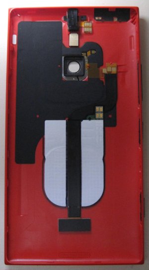
Step 2: Mark the ideal location of the Qi coil placed as shown above, so that the main body of the coil sits underneath the PMA flex, while the contact pads sit on top of the flex. Use a Sharpie or fine-point permanent marker to trace an outline of the coil body into the plastic shell, as well as lines along each side of the PMA flex sitting centered down the spine of the coil. Finally, trace an outline of the Qi coil contact pad onto the black PMA flex so that you know exactly where it will later be permanently positioned.
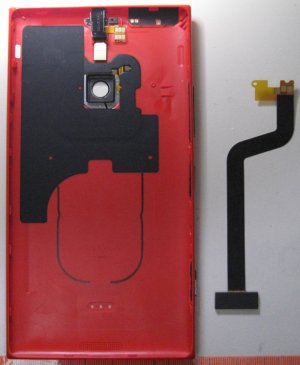
Step 3: Remove the Qi coil, then remove the PMA flex from the 1520 back shell by gently lifting the PMA flex contact pad near the camera lens up and away from the shell. Next, use a paper clip or smooth, flat tweezers (Style 2A from Techni-Tool) to gently lift up the PMA external contact plate up and away from the shell. This should completely release the PMA flex from the 1520 back shell. Set it aside, but protect it from contamination because you will need to recycle the adhesive at both ends of the flex. You should be left with a shell showing an outline of the 920 Qi coil placement as shown above.

Step 4: Using the close-up provided above, use Style 2A tweezers or something else with a sharp but blunt pointed edge to scrape away the black mylar mask off the PMA flex in the areas shown above. Note the outline of the 920 Qi coil drawn earlier just to the left, so you know where to make the alterations. Do not scrape into/past the copper traces in the PMA flex, or you'll have to make new holes further up the flex and insulate the ones you ruined. This is the riskiest part of the procedure, so take your time and do it right - and carefully. I do this part under a 20x scope...
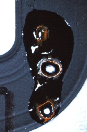
Step 5: Carefully tin the newly exposed copper on the PMA flex. Use solder flux. I recommend a 2 to 4mm soldering tip. No blobs. Do not add an excessive amount of solder, but add enough to make a good joint between the copper trace and the bus wire added in the next step.
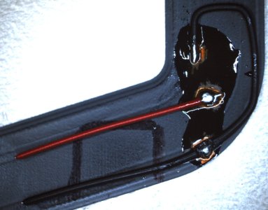
Step 6: Using the picture above as a guide, carefully solder a length of red and black solid core bus wire as shown, and be sure to leave sufficient length to solder to the 920 Qi coil charging pads. Ensure that there are no shorts between the two circuits (positive and negative), but DO make sure that both grounds (negative) are connected or the modification won't trigger charging.
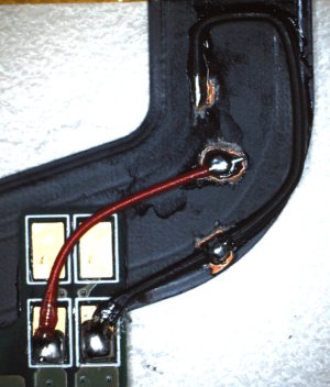
Step 7: Complete the soldering by placing the 920 Qi charging coil in the previously marked position on the PMA flex, so that the contact pad sits on top of the black PMA flex, and the Qi coil body sits under the PMA flex. Note that the gold pads on the 920 Qi charging coil are soldered to the Qi coild circuit board underneath, and they WILL try and come off or wiggle around when you heat the gold pad up. Be ready for this, and hold the gold pad in place to prevent movement. If the pad comes off, no big deal (don't try to replace it) - just solder the bus wire to the 4 tiny pads where the gold pad used to be. Once your soldering is complete, it should look like the picture above. Check it for shorts and correct any mistakes you find. Clean up any flux using 3M Novec or 99% Isopropyl alcohol. If you use Q-Tips to d?uche the area clean, use some scotch tape to remove any cotton fibers that will be shed by the Q-Tip(s). Make sure the area is dry of any solvents before proceeding.
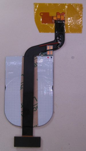
Step 8: (Optional) I recommend adding a strip of 3M laminating adhesive to the top spine of the 920 Qi charging coil to hold the PMA flex in place, and to act as strain-relief for the soldered connections. Since I recycled these 920 coils from broken 920's, I also added the same laminating adhesive to the other side of the Qi coil, but I think new coils already come with fresh adhesive on that side. Center the PMA flex down the spine of the Qi coil using the lines you drew on each side from step 2. Attach the PMA flex to the adhesive strip and press to seal.
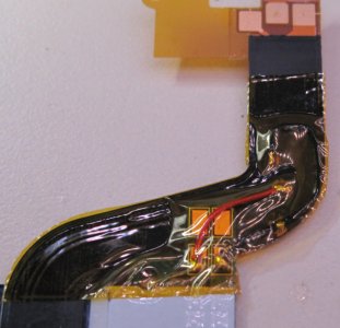
Step 9: Using Kapton tape or another polyamide tape, insulate the soldered areas as shown above. Use a sharp X-Acto blade to trim away any excess. Avoid wrinkling the tape.
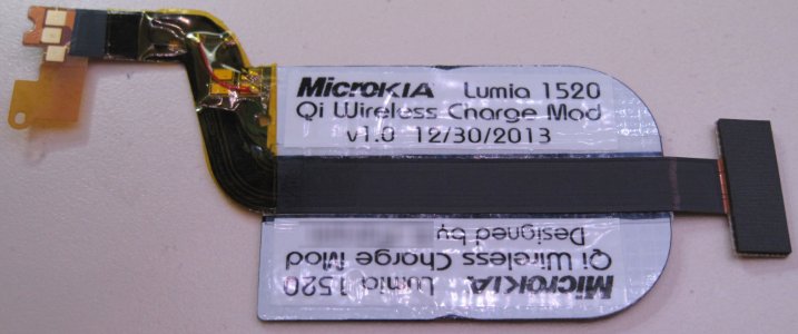
Step 10: The final product, with some "branding" added. This is ready to install in any AT&T 1520.
Step 11: Remove the two rubber spacers in the back shell, that normally sit on either side of the PMA flex (if you haven't already).
Step 12: Remove the double-sided adhesive backing on your 920 Qi coil and get it into position in the back shell, but don't press it down to seal just yet. First verify that the top part of the PMA flex fits into the keyway near the camera lens and press it down to re-activate the old adhesive. Clean off any finger oil you get on the gold contact plate. Then press the external contact PMA flex plate back into the holes in the shell (this may require more pressure than you think). Once those two ends of the PMA flex are in place, the Qi coil should already be centered right where it needs to go. Gently press to seal it into the back shell.
Step 13: Re-assemble the device and test your modification.
Ok, I think that's probably the limit of my contributions on this matter. Good luck, guys, and I hope you'll kick AT&T in the knuts if the opportunity presents itself. Better still, you could fuƈk with them and take your newly modified 1520 to an AT&T store, and "shop" for Qi-chargers. Have your 1520 out, in hand. When they see that you're trying to shop for a Qi charger for your 1520, they'll bravely try to be the hero and correct you towards the PMA solution. Then you can correct them and make THEM jealous... Muhahahaha... (insert sinister smirk here) :winktongue:
Cheers,
SonarTech
Let's begin.
Step 1: Open the 1520 and lay out the back shell with the PMA flex visible.

Step 2: Mark the ideal location of the Qi coil placed as shown above, so that the main body of the coil sits underneath the PMA flex, while the contact pads sit on top of the flex. Use a Sharpie or fine-point permanent marker to trace an outline of the coil body into the plastic shell, as well as lines along each side of the PMA flex sitting centered down the spine of the coil. Finally, trace an outline of the Qi coil contact pad onto the black PMA flex so that you know exactly where it will later be permanently positioned.

Step 3: Remove the Qi coil, then remove the PMA flex from the 1520 back shell by gently lifting the PMA flex contact pad near the camera lens up and away from the shell. Next, use a paper clip or smooth, flat tweezers (Style 2A from Techni-Tool) to gently lift up the PMA external contact plate up and away from the shell. This should completely release the PMA flex from the 1520 back shell. Set it aside, but protect it from contamination because you will need to recycle the adhesive at both ends of the flex. You should be left with a shell showing an outline of the 920 Qi coil placement as shown above.

Step 4: Using the close-up provided above, use Style 2A tweezers or something else with a sharp but blunt pointed edge to scrape away the black mylar mask off the PMA flex in the areas shown above. Note the outline of the 920 Qi coil drawn earlier just to the left, so you know where to make the alterations. Do not scrape into/past the copper traces in the PMA flex, or you'll have to make new holes further up the flex and insulate the ones you ruined. This is the riskiest part of the procedure, so take your time and do it right - and carefully. I do this part under a 20x scope...

Step 5: Carefully tin the newly exposed copper on the PMA flex. Use solder flux. I recommend a 2 to 4mm soldering tip. No blobs. Do not add an excessive amount of solder, but add enough to make a good joint between the copper trace and the bus wire added in the next step.

Step 6: Using the picture above as a guide, carefully solder a length of red and black solid core bus wire as shown, and be sure to leave sufficient length to solder to the 920 Qi coil charging pads. Ensure that there are no shorts between the two circuits (positive and negative), but DO make sure that both grounds (negative) are connected or the modification won't trigger charging.

Step 7: Complete the soldering by placing the 920 Qi charging coil in the previously marked position on the PMA flex, so that the contact pad sits on top of the black PMA flex, and the Qi coil body sits under the PMA flex. Note that the gold pads on the 920 Qi charging coil are soldered to the Qi coild circuit board underneath, and they WILL try and come off or wiggle around when you heat the gold pad up. Be ready for this, and hold the gold pad in place to prevent movement. If the pad comes off, no big deal (don't try to replace it) - just solder the bus wire to the 4 tiny pads where the gold pad used to be. Once your soldering is complete, it should look like the picture above. Check it for shorts and correct any mistakes you find. Clean up any flux using 3M Novec or 99% Isopropyl alcohol. If you use Q-Tips to d?uche the area clean, use some scotch tape to remove any cotton fibers that will be shed by the Q-Tip(s). Make sure the area is dry of any solvents before proceeding.

Step 8: (Optional) I recommend adding a strip of 3M laminating adhesive to the top spine of the 920 Qi charging coil to hold the PMA flex in place, and to act as strain-relief for the soldered connections. Since I recycled these 920 coils from broken 920's, I also added the same laminating adhesive to the other side of the Qi coil, but I think new coils already come with fresh adhesive on that side. Center the PMA flex down the spine of the Qi coil using the lines you drew on each side from step 2. Attach the PMA flex to the adhesive strip and press to seal.

Step 9: Using Kapton tape or another polyamide tape, insulate the soldered areas as shown above. Use a sharp X-Acto blade to trim away any excess. Avoid wrinkling the tape.

Step 10: The final product, with some "branding" added. This is ready to install in any AT&T 1520.
Step 11: Remove the two rubber spacers in the back shell, that normally sit on either side of the PMA flex (if you haven't already).
Step 12: Remove the double-sided adhesive backing on your 920 Qi coil and get it into position in the back shell, but don't press it down to seal just yet. First verify that the top part of the PMA flex fits into the keyway near the camera lens and press it down to re-activate the old adhesive. Clean off any finger oil you get on the gold contact plate. Then press the external contact PMA flex plate back into the holes in the shell (this may require more pressure than you think). Once those two ends of the PMA flex are in place, the Qi coil should already be centered right where it needs to go. Gently press to seal it into the back shell.
Step 13: Re-assemble the device and test your modification.
Ok, I think that's probably the limit of my contributions on this matter. Good luck, guys, and I hope you'll kick AT&T in the knuts if the opportunity presents itself. Better still, you could fuƈk with them and take your newly modified 1520 to an AT&T store, and "shop" for Qi-chargers. Have your 1520 out, in hand. When they see that you're trying to shop for a Qi charger for your 1520, they'll bravely try to be the hero and correct you towards the PMA solution. Then you can correct them and make THEM jealous... Muhahahaha... (insert sinister smirk here) :winktongue:
Cheers,
SonarTech
Laura Knotek
Retired Moderator
- Mar 31, 2012
- 29,451
- 63
- 48
Sonartech
New member
- Dec 17, 2013
- 43
- 0
- 0
SonarTech, how would this mod work if you have an international back? I ordered one and I'm curious if something can be done which doesn't require soldering. My skills in soldering are sub-mediocre at best.
The International 1520's going to come to you with a larger, pre-installed Qi-coil and flex (but no Qi-electronics). However, that particular flex only has two pins, to correspond with the two pins that are installed on an International 1520 PCB that already natively supports Qi (and the third pin's not even installed or used on an international 1520). As such, the International flex can't easily be used for this particular modification without a considerable amount more work, since you'll have to essentially add a third contact for the right-most trigger pin that's not present on that particular flex, or do something awful like solder a jumper to the pogo pin on the PCB itself - EeeeeKKkkk!!! :unhappysweat: That is most definitely off-the-table as it isn't reversible and is absolutely permanent.
So, all that the International back shell only offers you the ability to get rid of the 3 holes in the back shell for the PMA accessory charging cover. In my mod, you just use the same PMA flex to "plug" the holes, so that it doesn't look unsightly, and is at least completely sealed. I thought about cutting the original flex along with the 3 gold dots off as part of a modification step, but that would have required people to pot the holes with some kind of filler, and it would undoubtedly end up looking very ugly. Additionally, my mod's reversible since it doesn't made any changes to the phone electronics, and only changes an easily-replaceable flex. Also, you could unsolder the Qi Coil electronics, insulate the solder points on the flex, and paint it matte black to restore the original function of the flex even without replacement.
Unfortunately, the only real real solution I can think of to do this solder-free would be to design a custom flex that uses low-profile contacts or pogo pins to mate to the Qi-Coil electronics. Designing a flex is expensive, especially in low quantities (i.e., less than 10,000 units), and the flex would likely cost ~$20 each minimum. In short, it's just not worth it.
My solution simplifies this modification about as much as it can be simplified, using parts that are relatively easy to obtain. Unfortunately, fine soldering is a required skill, but that's one part I don't think we can easily work around.
SonarTech
Hemant Khatod
New member
- Dec 29, 2013
- 5
- 0
- 0
The International 1520's going to come to you with a larger, pre-installed Qi-coil and flex (but no Qi-electronics). However, that particular flex only has two pins, to correspond with the two pins that are installed on an International 1520 PCB that already natively supports Qi (and the third pin's not even installed or used on an international 1520). As such, the International flex can't easily be used for this particular modification without a considerable amount more work, since you'll have to essentially add a third contact for the right-most trigger pin that's not present on that particular flex, or do something awful like solder a jumper to the pogo pin on the PCB itself - EeeeeKKkkk!!! :unhappysweat: That is most definitely off-the-table as it isn't reversible and is absolutely permanent.
So, all that the International back shell only offers you the ability to get rid of the 3 holes in the back shell for the PMA accessory charging cover. In my mod, you just use the same PMA flex to "plug" the holes, so that it doesn't look unsightly, and is at least completely sealed. I thought about cutting the original flex along with the 3 gold dots off as part of a modification step, but that would have required people to pot the holes with some kind of filler, and it would undoubtedly end up looking very ugly. Additionally, my mod's reversible since it doesn't made any changes to the phone electronics, and only changes an easily-replaceable flex. Also, you could unsolder the Qi Coil electronics, insulate the solder points on the flex, and paint it matte black to restore the original function of the flex even without replacement.
Unfortunately, the only real real solution I can think of to do this solder-free would be to design a custom flex that uses low-profile contacts or pogo pins to mate to the Qi-Coil electronics. Designing a flex is expensive, especially in low quantities (i.e., less than 10,000 units), and the flex would likely cost ~$20 each minimum. In short, it's just not worth it.
My solution simplifies this modification about as much as it can be simplified, using parts that are relatively easy to obtain. Unfortunately, fine soldering is a required skill, but that's one part I don't think we can easily work around.
SonarTech
Agreed. I think this is the cleanest way given the situation we are in. Also, if you are planning on having a protective case for 1520( which I most definitely have- Thanks to be 1.5 year old) the three holes in the back is a moot point.
Sonartech
New member
- Dec 17, 2013
- 43
- 0
- 0
Hey, Guys -
I have a quick update for you. I dissected another flex and found a simpler way to jumper Trigger Negative and Negative. That bus wire jumper was a pain in the ʙutt, so here's an easier way to do it that won't require a jumper.
First, here's what the flex looks like when dissected:
? -T = Trigger (connect to negative to initiate charging)
? - = Circuit negative
? + = Circuit positive
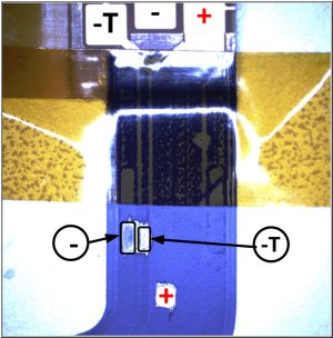
I found a spot where (-) and (-T) are very close together, and these can be easily jumpered with a small amount of solder. Positive (+) remains in the same place. Once the flex is prepped for soldering, this is what it ends up looking like:

Now, -T (trigger) and Negative are shorted in one, easy step. All that remains is to connect (-) and (+) from the Qi-coil.
Good luck!
SonarTech
I have a quick update for you. I dissected another flex and found a simpler way to jumper Trigger Negative and Negative. That bus wire jumper was a pain in the ʙutt, so here's an easier way to do it that won't require a jumper.
First, here's what the flex looks like when dissected:
? -T = Trigger (connect to negative to initiate charging)
? - = Circuit negative
? + = Circuit positive

I found a spot where (-) and (-T) are very close together, and these can be easily jumpered with a small amount of solder. Positive (+) remains in the same place. Once the flex is prepped for soldering, this is what it ends up looking like:

Now, -T (trigger) and Negative are shorted in one, easy step. All that remains is to connect (-) and (+) from the Qi-coil.
Good luck!
SonarTech
Sonartech
New member
- Dec 17, 2013
- 43
- 0
- 0
Sonartech...Have you found anywhere to purchase the flex cable for the AT&T 1520? I've looked but I haven't had any luck.
Haven't looked yet - I assume they're included as part of the back shell on the AT&T version. Being so new, they'll probably be hard to find for a while. Keep on eye on eTrade Supply:
Nokia Lumia 1520 Replacement Parts
SonarTech
superlawyer15
New member
- Feb 9, 2013
- 202
- 0
- 0
Similar threads
- Replies
- 20
- Views
- 6K
- Replies
- 25
- Views
- 5K
- Locked
- Replies
- 3
- Views
- 2K
- Replies
- 15
- Views
- 3K
Trending Posts
-
Windows 11 Power Icon Remotely changed! (Percentage Gone)
- Started by Fifth313ment
- Replies: 0
-
Forum statistics

Space.com is part of Future plc, an international media group and leading digital publisher. Visit our corporate site.
© Future Publishing Limited Quay House, The Ambury, Bath BA1 1UA. All rights reserved. England and Wales company registration number 2008885.
